Chapter 1 — Tape-Style Looper (Max)
This section introduces tape-style looping and is designed for those new to Max. However, it does assume a basic understanding of fundamental Max concepts: you should be familiar with the basic concepts of what a patcher is, what objects are, and how to connect objects before moving forward. Each subsequent chapter will build upon this foundational knowledge.

Figure 1-01
Introduction to Tape-Style Looping
Our first looper is inspired by early tape-based loopers that loop audio elements in relation to the timing determined by the physical length of the tape loop. This type of looper is well-suited for experimental musicians, drone artists, and others who prioritize creative exploration over precise loop timing. It is not ideal for the more common approach to live-looping, which typically involves overdubbing beats, melodies, and bass lines in a metrically synchronized manner. In later chapters, we will build live loopers that allow the loop length to be set interactively during your performance, providing options for both synchronous and asynchronous loops. The tape-style looper we are building here offers great creative possibilities, as demonstrated by artists such as Robert Fripp, Pauline Oliveros, and Brian Eno, among others, who have used tape-based systems.
For this project, we will use the tapin~/tapout~ pair of objects, which allows us to create a feedback loop with a predetermined loop duration set in milliseconds.
Setting Up Audio Input and Output in Max
For this patcher, audio enters the computer through an audio interface or a built-in microphone, is processed (looped, etc.) within Max, and is finally output through the audio interface or built-in speakers/headphones.
The handling of audio input and output is managed by two primary objects: adc~ (analog-to-digital converter) for audio input, and dac~ (digital-to-analog converter) for audio output. The tilde (~) in the names of these Max objects signifies that they are part of the MSP category of objects in the Max environment, which deals with digital signals—specifically, audio in this context. Max also features a variety of specialized objects, each with its own distinct identifiers: Jitter (video objects prefixed with “jit”), Max for Live (M4L) objects starting with “live,” MC (multichannel objects beginning with “mc”), as well as gen, RNBO, and more.
To begin, create a new blank patcher by navigating to File and selecting “New Patcher.” Following this, we will begin adding the necessary objects.
Let’s start with an adc~. As with all things Max, there are multiple ways to do this. We highly recommend learning shortcuts from the beginning.
In the unlocked patcher (the lock/unlock icon is in the lower left corner), and with the patcher selected (just click on it), press the letter “n.” This creates an empty object; type in ‘adc~’ (it should autofill at some point) and press Return. You should now see this:
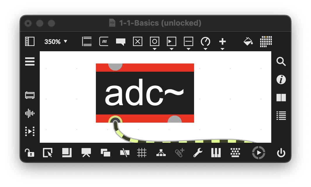
Figure 1-02
To view the audio settings for Max and your patcher, go to the “Options” menu and select “Audio Status…”. You can also open “Audio Status” by double-clicking your adc~ or dac~ in a locked patcher, by sending them an “open” message, or by looking in Max preferences.
In the Audio Status window, you can view, select, and adjust the specifics of your computer and audio interface, as well as settings related to CPU performance and scheduling. For now, we will leave these settings at their default values. The image below shows my sampling rate set to 48,000 Hz, with both the I/O Vector Size and Signal Vector Size set to 32.
Generally, smaller vector sizes result in lower latency, however, at the expense of increased CPU usage. Larger vector sizes reduce CPU load while increasing latency. Max patching almost always involves balancing this tradeoff between responsiveness and computational cost, making these settings particularly important.
The Overdrive option prioritizes message handling and audio processing over screen drawing. Enabling it can improve timing for audio tasks, but may make the user interface feel less responsive. Similarly, enabling the Scheduler in Audio Interrupt can improve synchronization, with the same potential side effect of UI sluggishness.
If something feels off while using a patcher—whether increased latency or a laggy interface—these settings are often the first place to experiment. Depending on your machine and the complexity of the patch, minor adjustments here can make a significant difference.
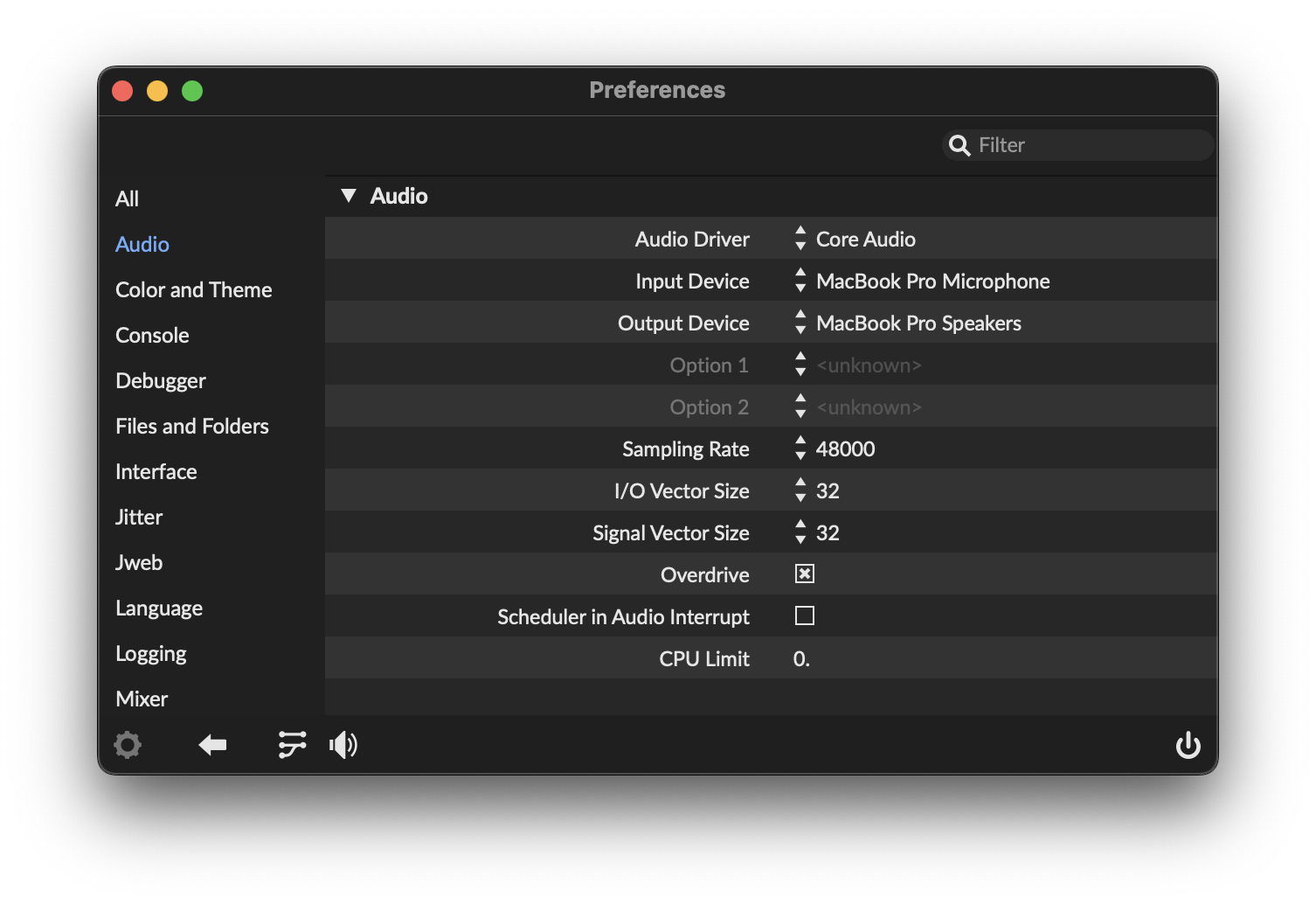
Figure 1-03
adc~ in its default state, as pictured below, is set to audio inputs 1 and 2 (in your computer or interface), which enter your patcher through the outlets at the bottom of the adc~ object. The top inlet is for messages (start, stop, on, off, open, et cetera).
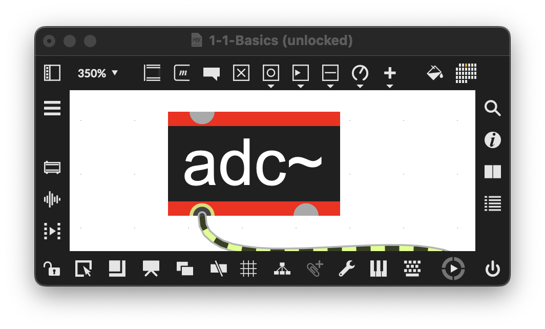
Figure 1-04
You can assign specific inputs to the adc~ by typing in a number or multiple numbers. As you can see below, there are now four outputs to the object that correspond to the input numbers entered.
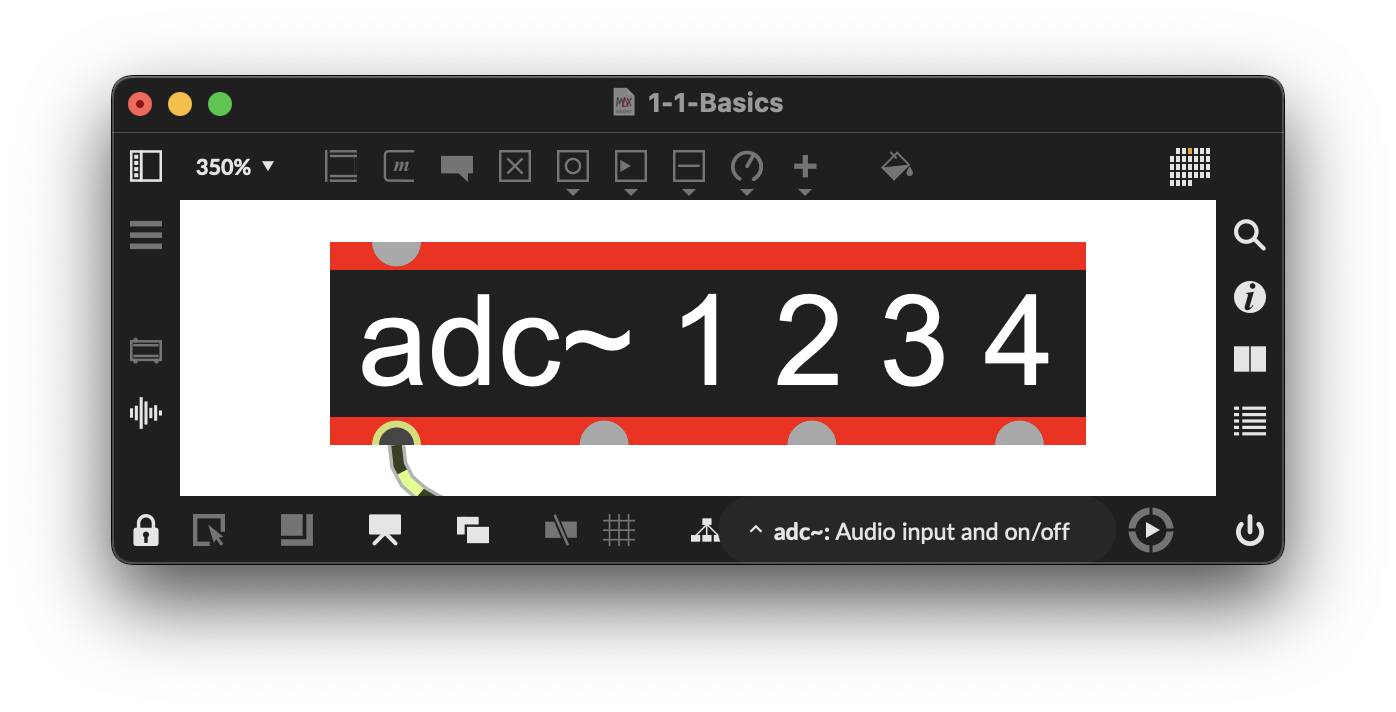
Figure 1-05
Numbers need not be sequential; you can type in discontiguous numbers that will correspond to those matching inputs or outputs
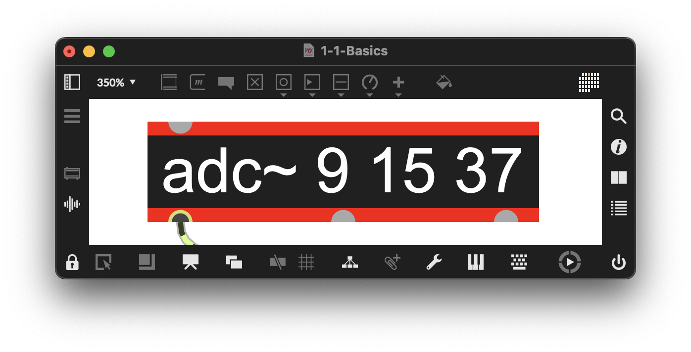
Figure 1-06
You can also type in a single number. For example, on my personal audio interface, the microphone input is 13, and you can see there is now a single output from the object.
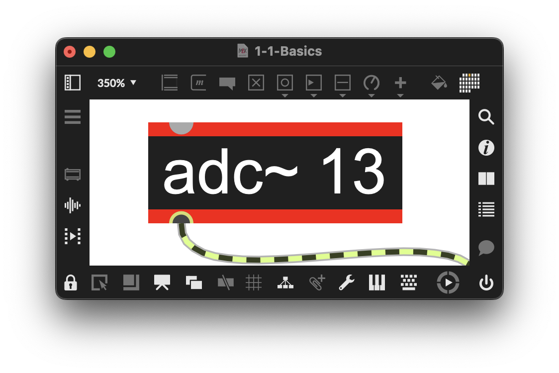
Figure 1-07
dac~ functions similarly regarding outputs. The object is set to outputs 1 and 2 by default, accessible from the inputs at the top of the object, which will be sent to your computer or audio interface.
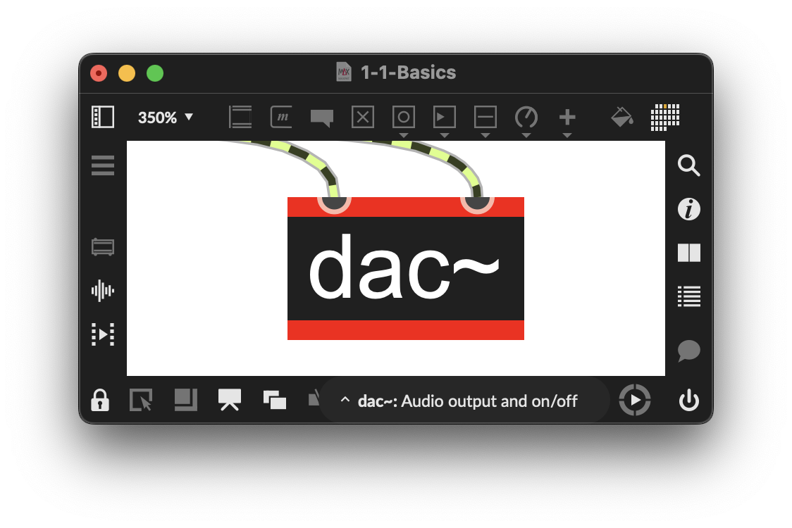
Figure 1-08
As with adc~ we can type in numbers (multiples or individual) that will correspond to your computer or interface.
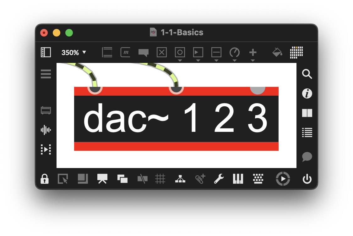
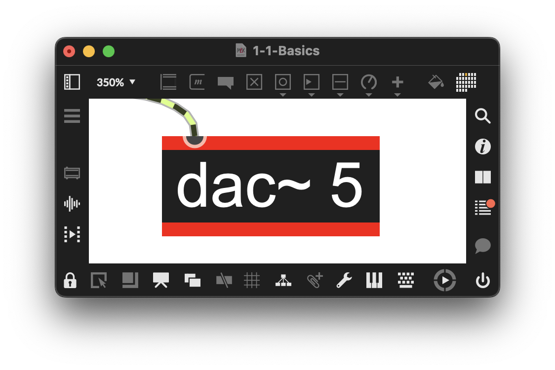
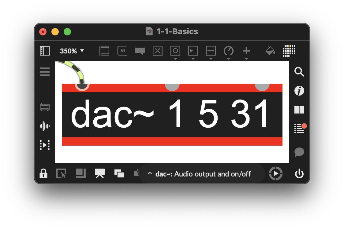
Figure 1-09
For this patcher, we will leave adc~ set to input 1 and dac~ in its default output settings of 1 and 2.
Audio input for the looper
Now that we have set up the input and outputs, let’s start adding the looper section to our patcher.
In the input stage, we will first create a section that allows audio from the adc~ to enter the looper. This will enable us to select the specific audio we want to loop. While we could have our patch continuously looping incoming audio, building this section gives you the option to be more selective about what you record into the loop.
For this patcher, we will use a Max gate~ object that “gates” the audio, i.e., blocking the input or letting it pass. Other options for accomplishing this task that you can explore include selector~, matrix~, or a combination of line and *~.
In the example below, we have added a gate~ between the adc~ and dac~.
The audio input (adc~) is connected to the right inlet of the gate~ object, and we have added a toggle to the left inlet. To quickly add a toggle, you can press the letter “t” in a blank space of the selected patcher. Alternatively, you can press “n” for a new object, then type “toggle,” or select the toggle option from the menu at the top of the patcher frame. It’s important to note that when typing the name, there is no “~” at the end. This absence of any additional identifier indicates that this is a Max object, which is message-based, whereas MSP objects (those with a “~”) are signal-based.
To connect the objects, click and drag from the corresponding output (located at the bottom of the object) to the appropriate input (found at the top of the object). You can also drag from an input to an output. It’s essential to remember that each inlet and outlet has a specific assigned task or function, so ensure that you connect the correct inputs and outputs carefully.
Each type of object, in this case, Max and MSP, will also have its own identifiable style of cable. The Max objects’ (messages) default cable is solid gray with an outline, and the MSP (signals) is the yellow-striped cable.
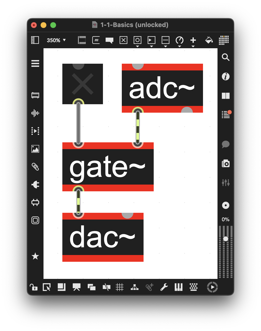
Figure 1-10
To use the patcher effectively, ensure that it is locked (indicated by the lock icon in the lower-left corner) and that the audio for the patcher is turned on (controlled by the on/off switch in the lower-right corner). When you press the toggle, it will highlight the “X,” indicating that the toggle is “on.” This action sends out a “1” from the toggle, which opens the gate~ and allows audio to pass through. Conversely, when you deselect the “X” on the toggle, it sends a “0,” closing the gate. Remember, the audio must be turned on for MSP objects to function properly.
When building the input section, it’s important to consider audio clicks. These clicks can happen for various reasons, but in this case, they often occur when audio is gated, causing an instantaneous switch from no signal to a signal or vice versa. Due to the laws of physics, speakers cannot move from one position to another instantaneously. As a result, the speaker's attempt to shift rapidly creates a clicking sound. One way to avoid this click is to create an amplitude ramp (fade in/out) up from 0. as you turn the gate on, and down to 0. as you turn off the gate. This ramp can be accomplished by adding the ramptime attribute to the gate~. This attribute can be adjusted to your preference, ranging from a short fade, such as 50 ms, to eliminate most clicks, to a longer fade that may better suit your creative goals. Here is the same configuration as above with the added @ramptime attribute. Ramptime can also be adjusted by sending a message. To add a message, use the shortcut “m” on an unlocked selected patcher, then click and drag to create a connection. While it is not necessary to use a message when setting it with the @ramptime attribute, sending a message allows for more creative control over ramptime while you are playing. You can incorporate a variable ramptime using the $1 sign in your messages, with a number object connected to the messages’ left input.
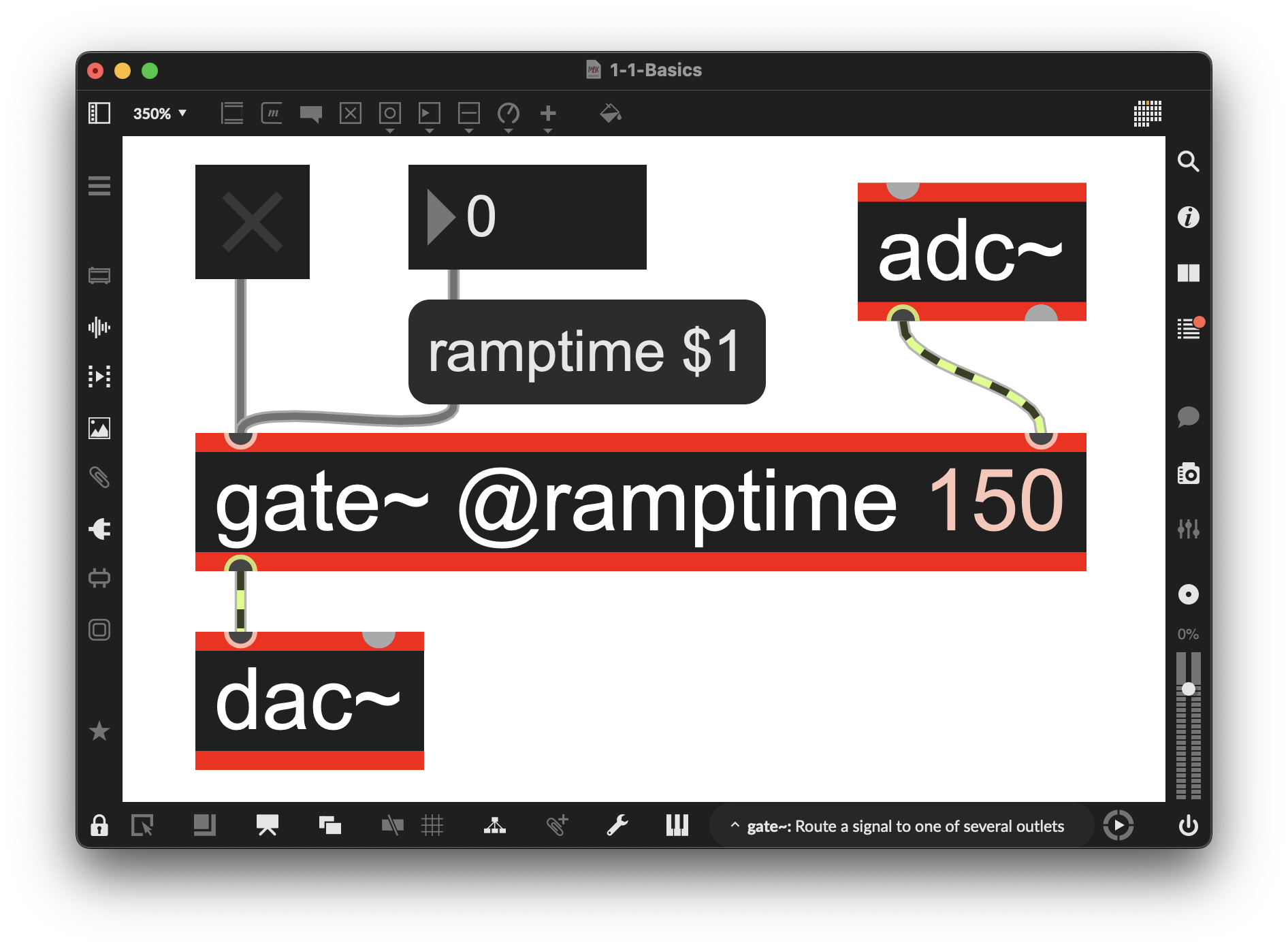
Figure 1-11
Creating the Looper with tapin~/tapout~
(Example Patcher: 1-1-Basics)
One of the main characteristics of a tape loop is its fixed length. Similar to a tape loop system, the first step for us is to determine the length of the loop. In this section of the patcher, we will utilize the tapin~/tapout~ pair to create a feedback loop that operates similarly to a tape loop on a tape player.
tapin~/tapout~
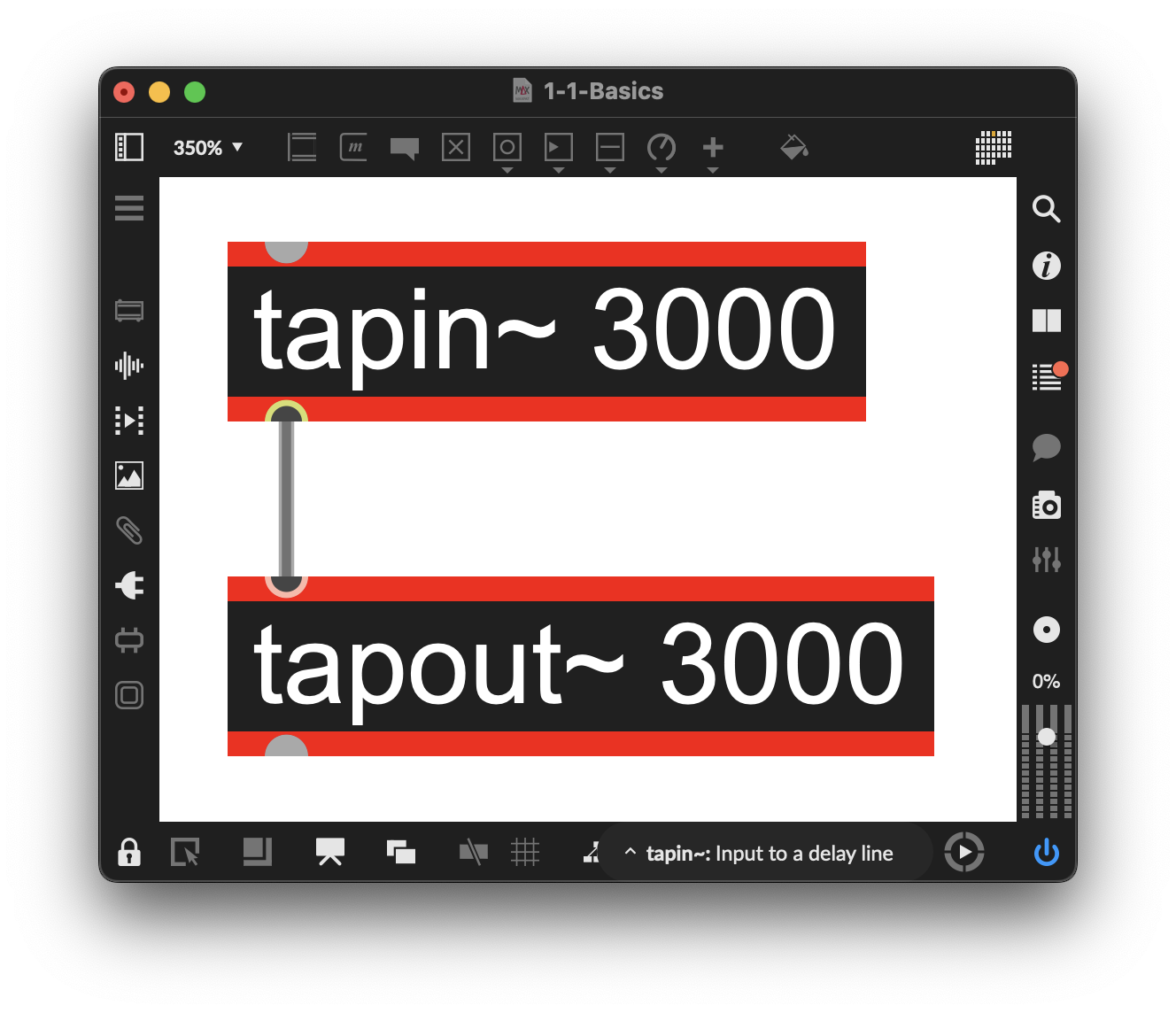
Figure 1-12
tapin~ takes as its input a signal and copies that signal into a delay line. The maximum available delay time (set in milliseconds) for this particular tapin~ is 3000 (3 seconds). The tapout~ object plays that signal back at its set delay time (3000, the maximum available, is used for this example), also set in milliseconds. The tapout~ delay time can be any number equal to or less than the tapin~ setting. This pair of objects is unique in the Max/MSP world in that they cannot function without each other, they must always exist in tandem. They are also unique MSP objects, in that the cable that connects them is not an audio cable, but a Max cable that exists to show the objects share a delay line. Remember: the delay used (set in tapout~) cannot exceed the delay available (set in tapin~). You can add multiple delays to tapout~ as long as each is equal to or less than the total delay available set by the tapin~. Each delay number will create its own output, as well as an input to adjust the delay value if desired. The example below has three delays, each with its own output.
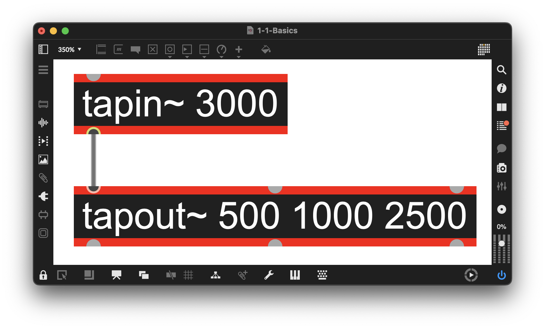
Figure 1-13
For this patcher, we will leave the tapin~/tapout~ pair with a single delay line at 3000 ms to emulate a 3-second tape loop.
The next step is to add a feedback loop so that the recording continuously loops, allowing us to overdub any audio we input. One of the other unique features of the tapin~/tapout~ pair is that you can create a feedback loop…and it won’t crash the patcher. It can, however, create loud audio moments, so we will also need to add control for the amount of signal going into the feedback loop, as too much signal can lead to an audio explosion. Additionally, we may want the audio to fade out as it cycles through the feedback loop. For this, we will add a *~ into the loop and have it default to multiplying the looping signal by “.9,” a safe value to start with.
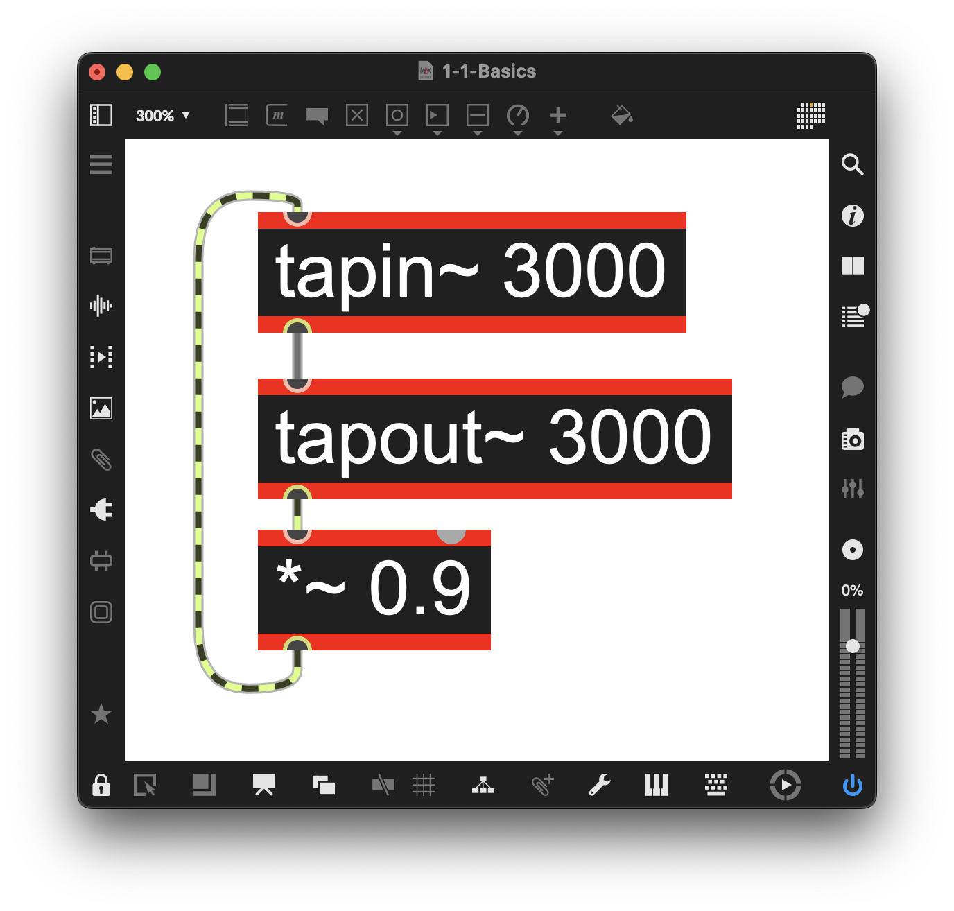
Figure 1-14
Adding Clear
One last thing, let’s add the clear message to our tapin~, which, as the name suggests, will clear the delay line.
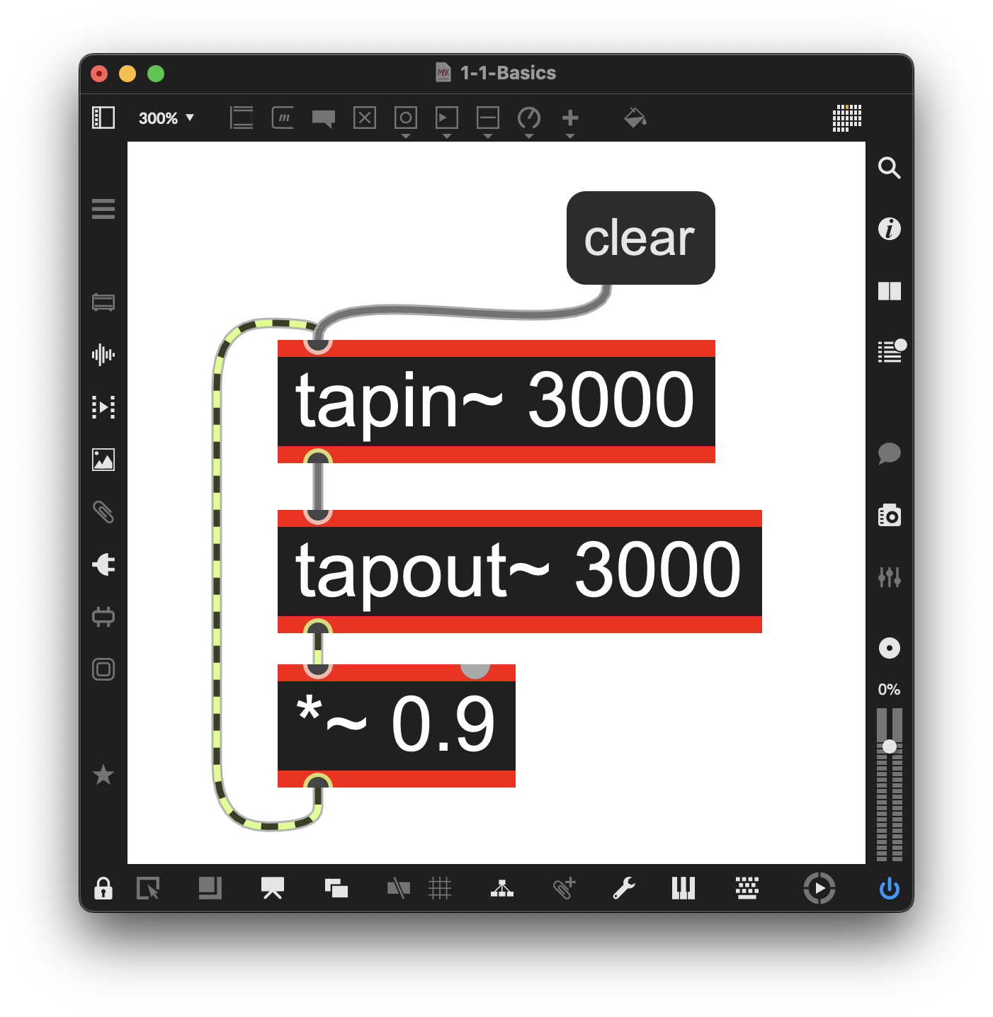
Figure 1-15
Now let’s connect our adc~ with our previously made gate~ and dac~, and you have a basic three-second looper where you can let audio in with the gate~.
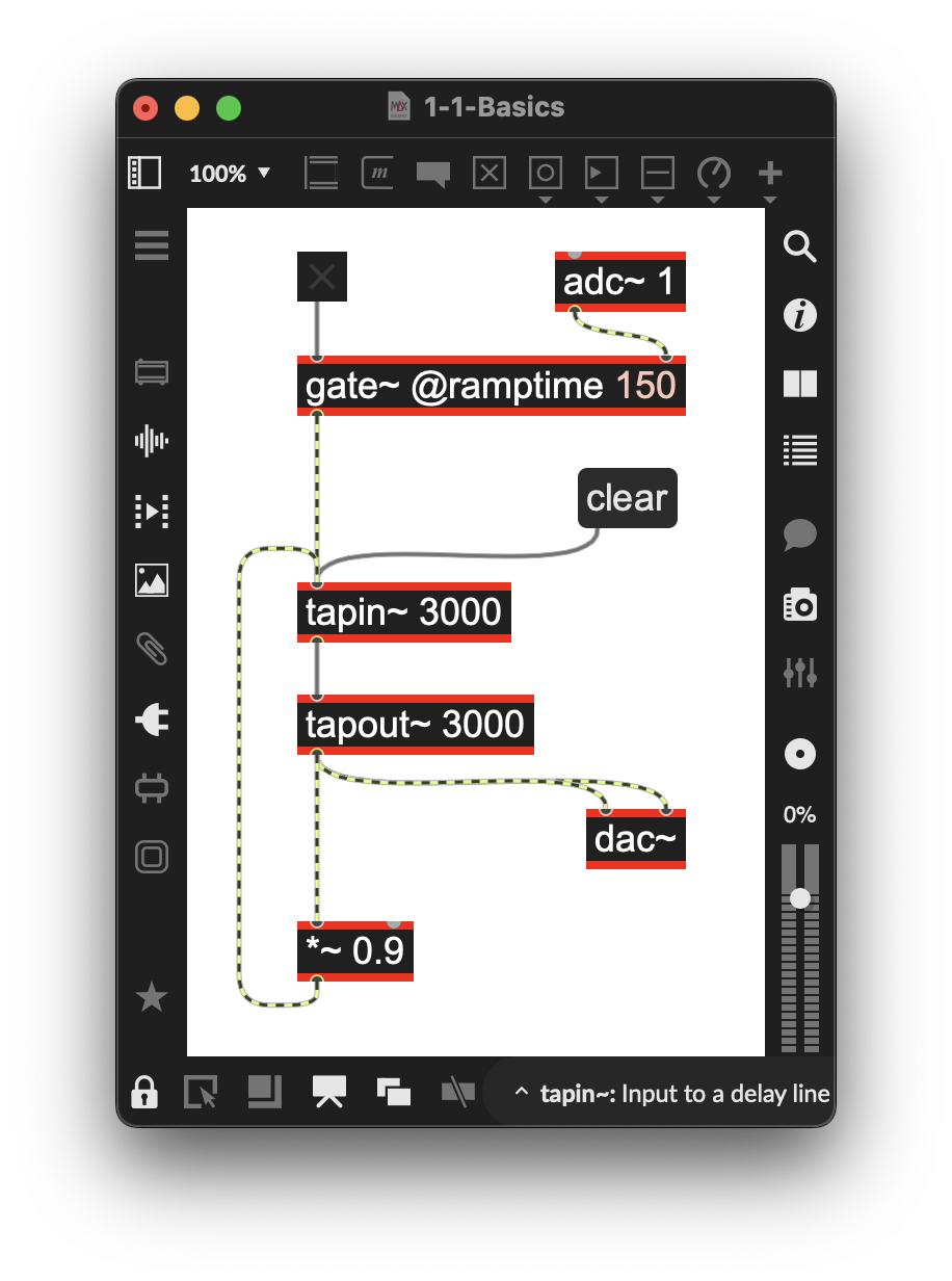
Figure 1-16
Adding Feedback and Amplitude Control
You can add a float number display/GUI by creating a new object and typing flonum, or you can simply press “f” in a blank spot of your unlocked patcher.
Select the flonum and in the Inspector (button with a circle and an “i” on the sidebar or select “Inspector” in the Object Menu), set the Minimum to “0.” and the Maximum to “.9.” This will create a limit to the minimum/maximum level of the audio as it loops (feeds back) into itself, again, preventing audio explosions as well as allowing for creative fade outs of the audio as it loops through the system.
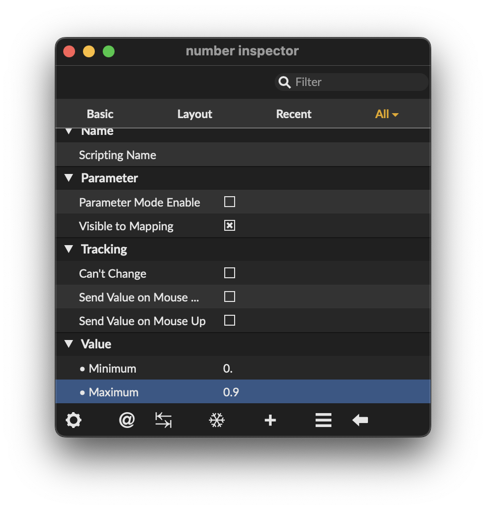
Figure 1-17
Connect the flonum to the right input of the *~. This will allow you to adjust the feedback from 0. to .9
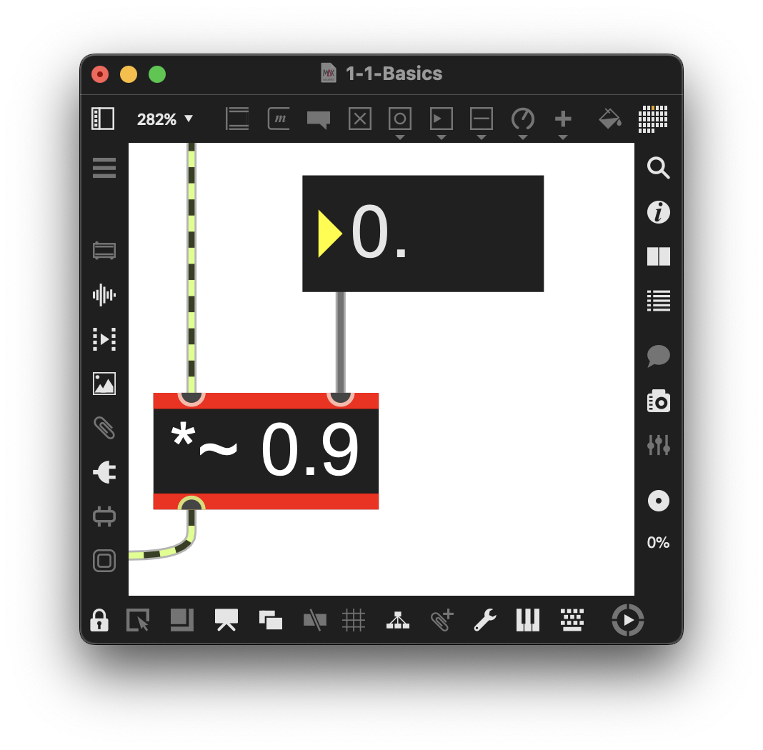
Figure 1-18
The patcher should now look something like this:
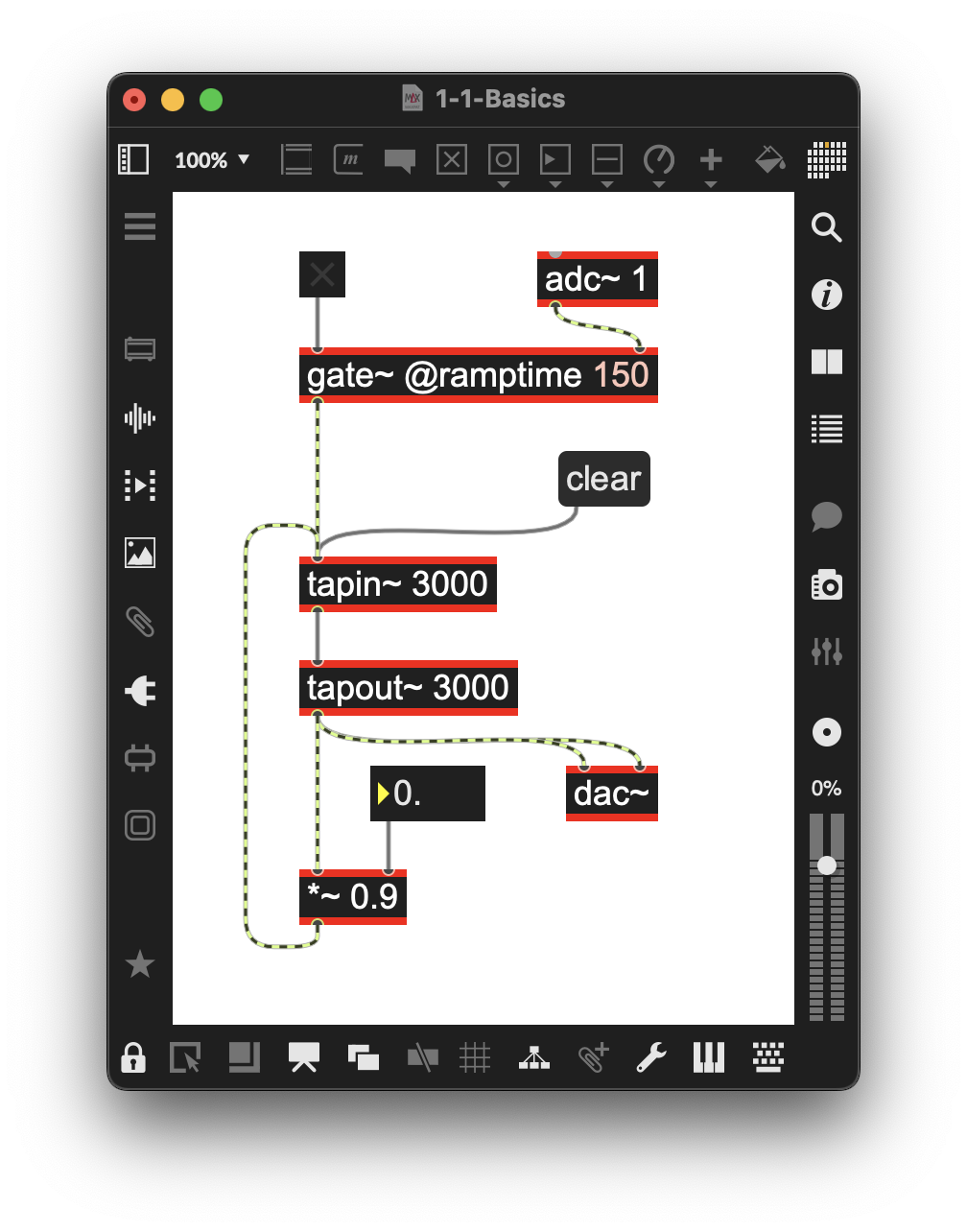
Figure 1-19
Mixing Options for Live Looping
(Example Patcher: 1-2-Mixing)
An important part of live looping is the ability to mix the level of your voice/instrument in relation to the level of your loop. Let’s add this capability to our patcher.
- Add a mono live.gain~ named Input. Throughout this text and in our private work, we prefer live.gain~ because it includes metering and naming in the object, and many of these patchers may end up in Max for Live. To name them, select the object, open the Inspector, and find the name parameters.
- Add a mono live.gain~ named Loop for the loop level
- Add a mono live.gain~ named Dry for the dry (unprocessed) level of the Input
- Add a mono live.gain~ called Output to monitor levels at the dac~. If we plugged both the Loop and Dry directly into the dac~, we would not see their combined level (sum), which could be a hidden source of clipping (generally considered undesirable distortion). This is important: do not sum audio where the summed level is invisible. Here we sum the audio at a live.gain~ allowing us to see if there is any clipping.
Note the mostly vertical nature of this patcher in its basic state. This allows us to clearly see the flow of outlets to inlets in the patcher. We could build the patcher with objects side by side, but as the patcher grows in complexity, the cable routing becomes increasingly challenging to follow.
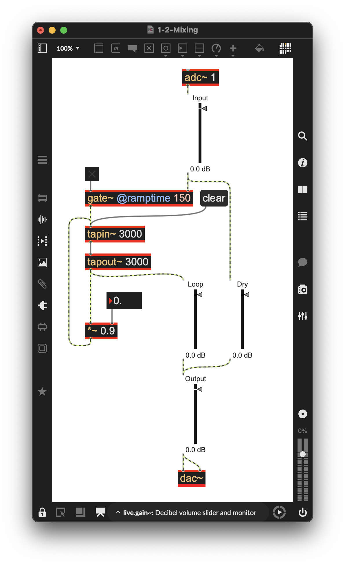
Figure 1-20
On/Off Control with the Spacebar
Before moving on to processing within the loop, let’s add one more feature. Many audio programs use the spacebar to turn the software on and off. Let’s build a spacebar on/off.
Add a toggle to the dac~ to turn audio on and off. Click on the patcher where you would like the toggle, press “t,” and connect the toggle to the dac~.
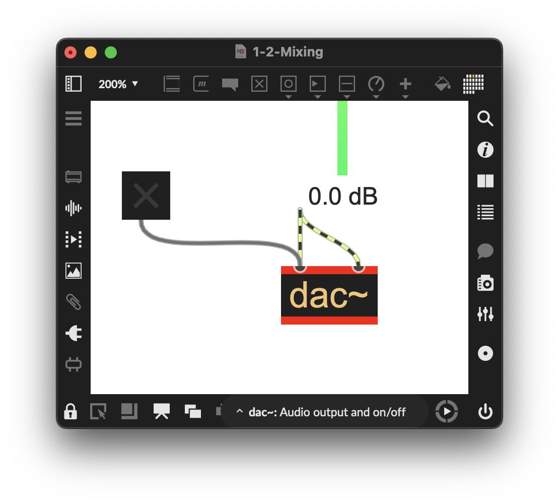
Figure 1-21
Now, above the toggle with room for another object between, press “n” for a new object and type “key.” The key object reports keyboard output, including, among other things, the ASCII key number of whatever you are typing. If you open the help file for the key object, you can see all the features it offers.
Knowing that the ASCII code for the spacebar is 32 (as discovered in the help file), we will add a new object, select (sel is the abbreviated name of the same object), with the argument 32. So, when the select object receives the message “32” from key, select outputs a bang. Now whenever I press the spacebar, key outputs a “32” that select sees, that 32 then outputs a bang that will turn on or off the toggle (the opposite of what it is currently set), and turn on/off the audio via the dac~.
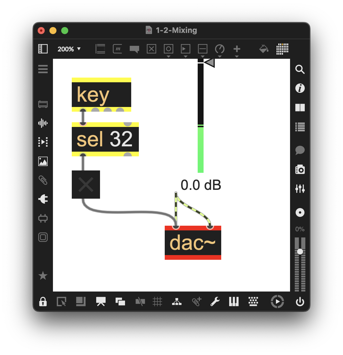
Figure 1-22
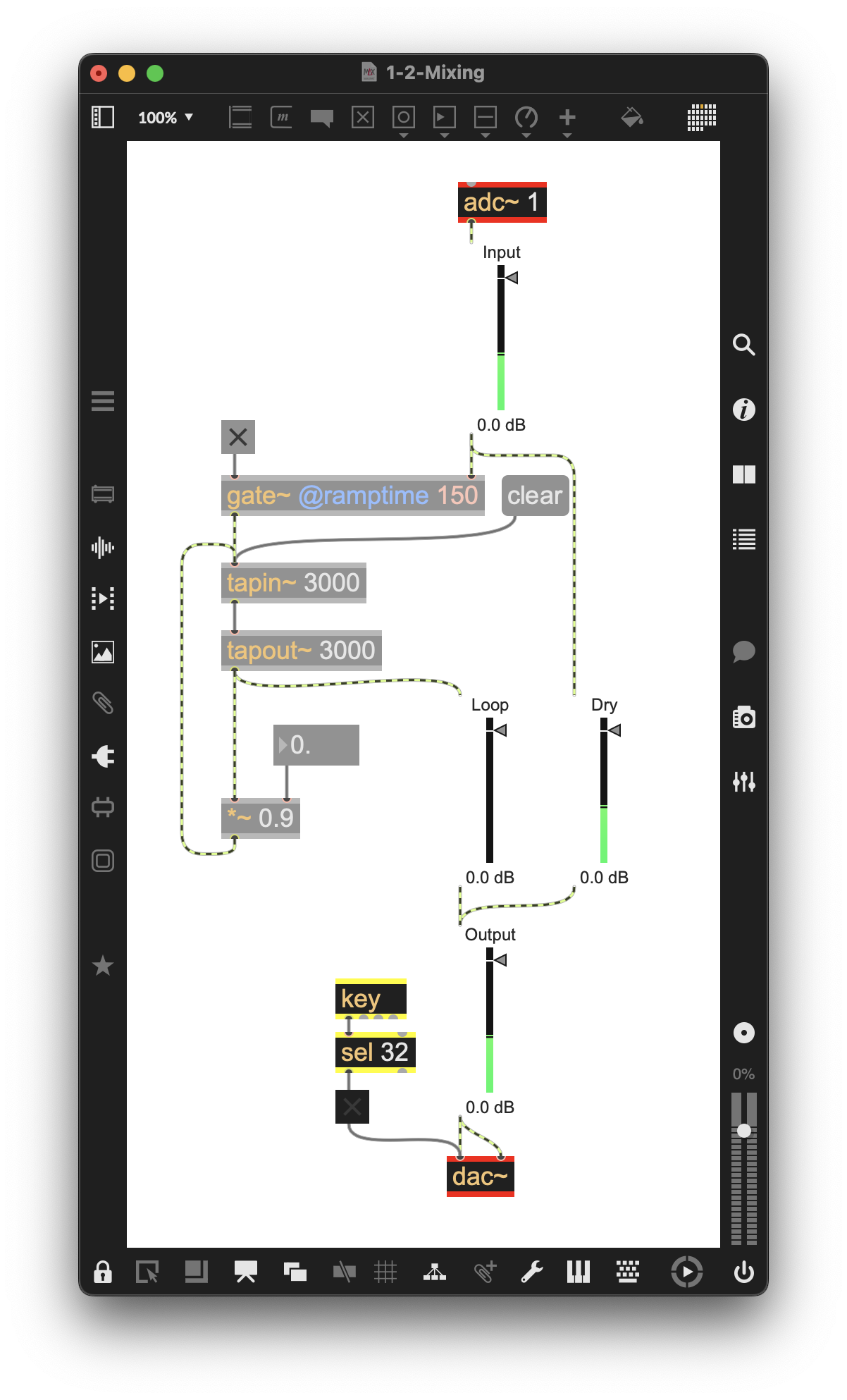
Figure 1-23
Varying the Length of the Loop
(Example Patcher: 1-3-Length)
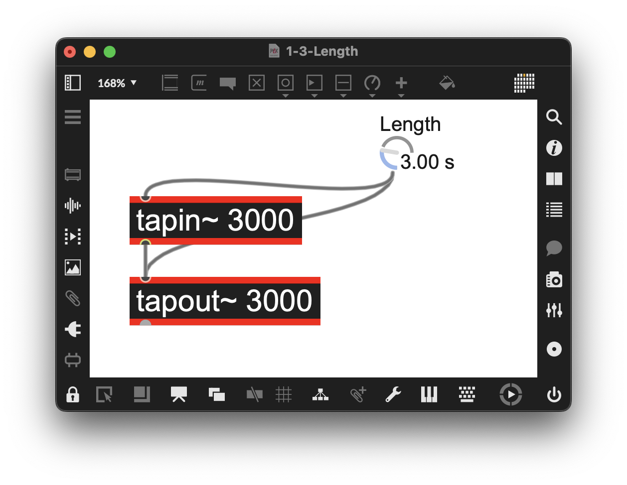
Figure 1-24
To vary the length of the loop, we have added a live.dial named Length using the parameter settings below: Float, range of 1. to 60000., initial 3000, and Unit Style of “Time (ms)”
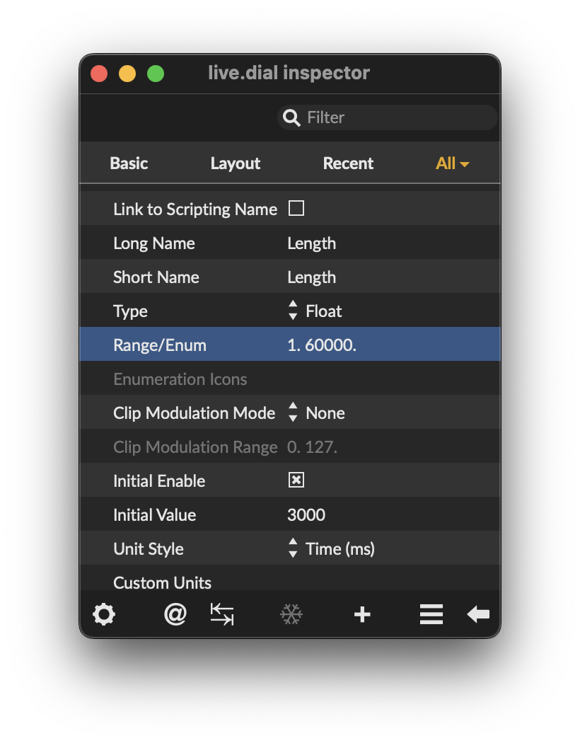
Figure 1-25
Be aware that changing the time of tapin~ clears the delay line. This can make a noise that may or may not be considered undesirable. So it is best to change the length/time when the delay line is empty.
Adding Processing in the Loop
(Example Patcher: 1-4-Processing)
One of the joys of working with feedback loops is the ability to create variations of the audio as it passes through the loop each iteration. For the following examples, we will add several options for signal processing within the loop:
- We will add a switch, in this case gate~, to route audio straight to the loop with or without processing, commonly called a “bypass.”
- We will then create three options for processing in the loop, each with a bypass:
- Add the ability to transpose the output to change its pitch in the loop
- Add a lowpass filter to the processing chain in the loop
- Add a little judicious distortion/degradation to our processing chain in the loop.
Building a Bypass
Adding the ability to route the audio signal into the processing stage or bypass it is the next step in building our looper. We can use the gate~ object we have used earlier to do this. When we used it in the input/record stage, it either enabled or disabled audio input. However, now we want to have two outputs for our gate—one outlet to bypass it into the loop, and one outlet to route it to the processing stage. To do so, we add the gate~ object and give it an initial argument of “2” to create two outlets. We also add a @ramptime 50 attribute to minimize clicks, as we did before.
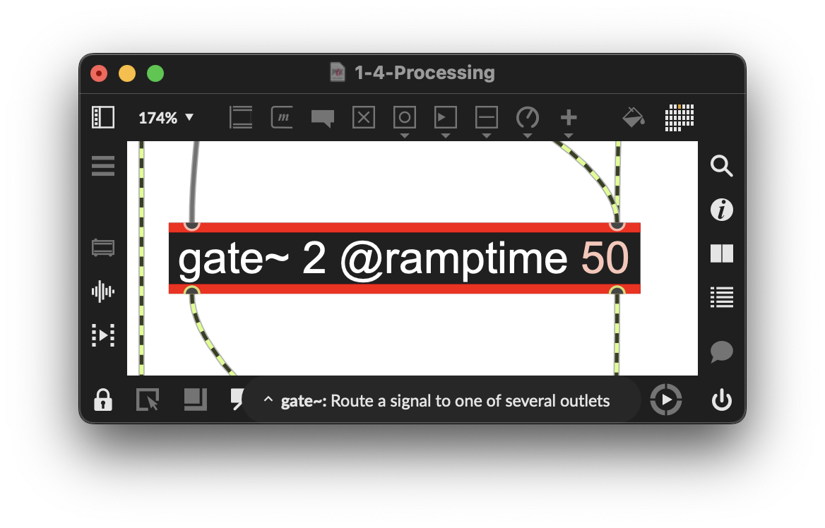
Figure 1-26
We already know that a toggle object sends either a 0 or 1 as its output. The gate~ 2 @ramptime 50 object we have added now has three possible states:
- 0: no output at all
- 1: route output to the first output of the gate~ object
- 2: route output to the second output of the gate~ object.
For our purposes, we never want to send a value of 0 to the gate~ object for this patcher (that would turn everything off); we need to send a value of 1 or 2. We can easily do this by adding 1 to the output value of the toggle object with the + object. This makes its output of 0 or 1 become 1 or 2 with the addition.
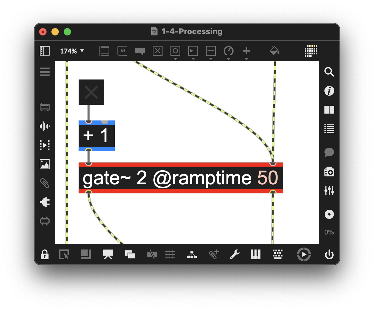
Figure 1-27
Since gate~ defaults to 0, we need to ensure the toggle outputs 0 initially. This allows a 1 to be added, which then opens the first output. This initial output on opening is set in the toggle’s inspector. Select the toggle in an unlocked patcher. Ensure the inspector window is open and displays “All” at the top. Then, select “Parameter Mode Enable.”
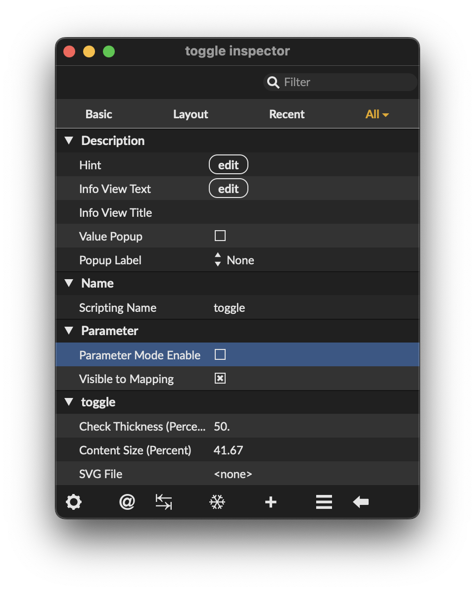
Figure 1-28
This will display a list of options. In these options, select “Initial Enable” and set the “Initial Value” to “0.”
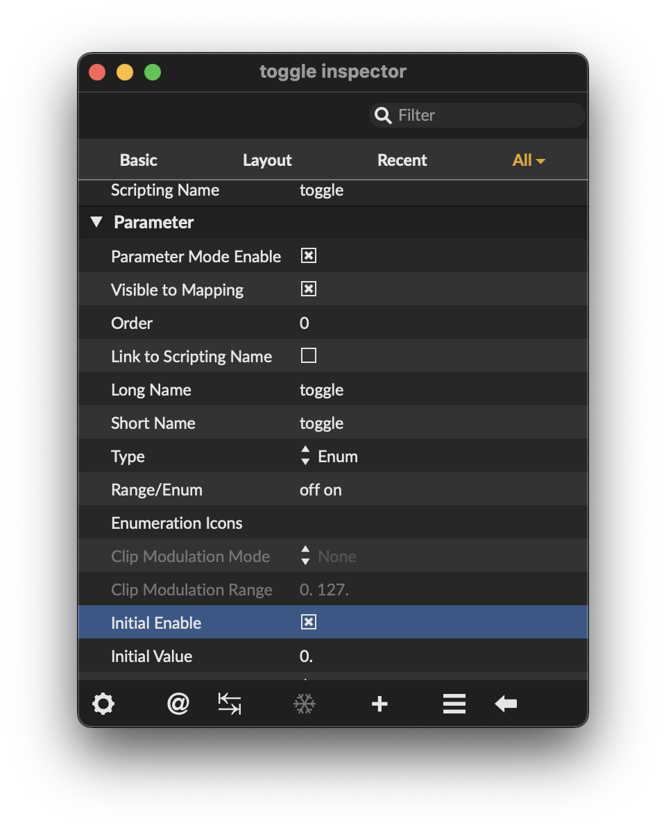
Figure 1-29
When the patcher is loaded, the toggle, in combination with the + 1, will automatically set the gate~ to the first outlet.
Pitch Change
Let’s create a named bypass for pitch processing, replacing the above toggle with a named live.text object.
As we continue to patch our way through this book, we will be using a live.text object where you might expect to see a toggle object. There are two reasons for doing this:
- A live.text object lets us create buttons and toggles with clear labels referring to the function being controlled.
- Many of the patches we are creating may ultimately become Max for Live Plugins, and the Live object set is designed to be used in this environment.
Add a live.text object. Use the live.text object’s Inspector, locate the Value section of the Inspector, and type in the text we want to appear (since our text includes spaces, we will need to put what we type in in quotes). For the first example, we use “Pitch Off” and “Pitch On.” We now have (compared to a highlighted “x”) a clear label indicating the function being selected.
As you did with the basic toggle, select Initial Enable in the object’s Inspector and set the Initial Value to 0 (you do not need to enable Parameter Mode in Live objects).
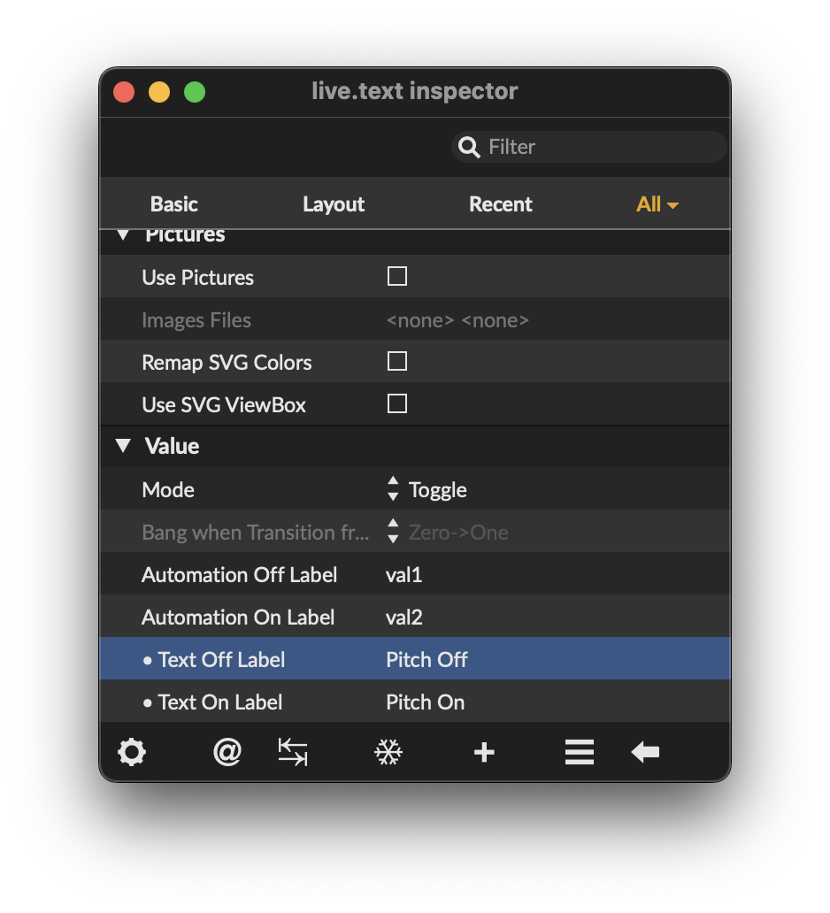
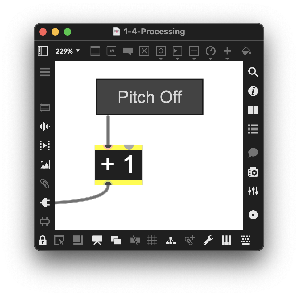
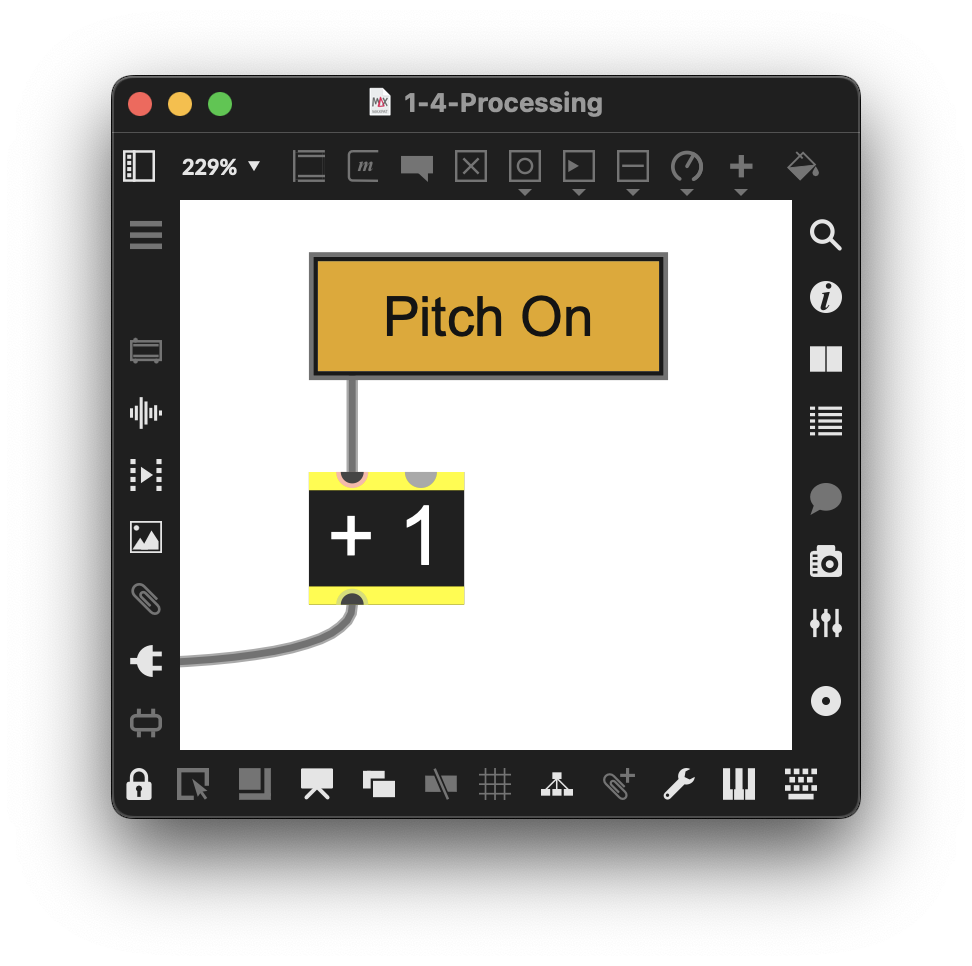
Figure 1-30
We will now introduce pitch transposition to our looper, allowing the pitch to change by a selected amount each time the audio passes through the loop. The Max pitchshift~ object offers a straightforward method to implement this feature.
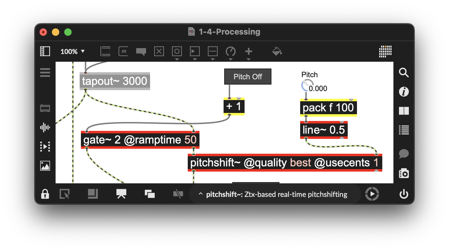
Figure 1-31
Create a new pitchshift~ object and add the @quality best and @usecents 1 attributes. Setting the @usecents attribute to 1 configures the pitchshift~ object’s second inlet to accept a pitch change number value and convert that to cents (cents is a unit of measure for the pitch transposition— each half-step interval is equal to 100 cents). We will use an incoming signal value along with a line~ object to smooth the transition between settings as you select the value with the dial. Notice we used a live.dial object here, replacing the regular dial object for the same reason we did toggle with a live.text object: labeling of the function controlled and ease-of-use with Max for Live.
In the Parameter section of the live.dial object’s Inspector, give the live.dial object a label “Pitch,” set the range to -2400 and 2400 (which corresponds to a pitch change of two octaves up or down), and set the Initial Enable with an Initial Value of 0. We also changed the Unit Style to Custom and set the Custom Units to “%.3f” (a sprintf-style character string that instructs the dial to display three decimal places of accuracy). We chose cents for pitch values—rather than semitones or another option—to support the microtonal pitch variation that decimal places allow us to create. (For more about sprintf, check out the sprintf object help file or Max Reference page.)
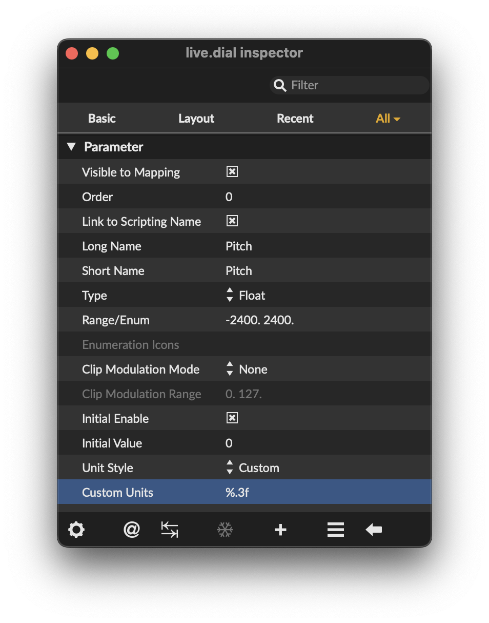
Figure 1-32
Lowpass Filter
Next, let’s add a lowpass filter to the loop processing. For this example, we will use a onepole~ object, which is a simple and efficient one-pole lowpass filter.
Once again, we will use a gate~ object to set up our signal routing bypass. Notice that the first output from the previous gate~ object we added earlier is connected to both the input of the new gate~ and the output of the pitchshift~. Since the signal in the first gate~ is only going to one of the outputs (bypassed or pitch-shifted), only one output will be passed to this new gate~.
As before, we will add a combination of live.text object and + 1 to our gate and name it “LP Off” and “LP On” using the live.text object’s Inspector, with an initial value for the enable set to 0.
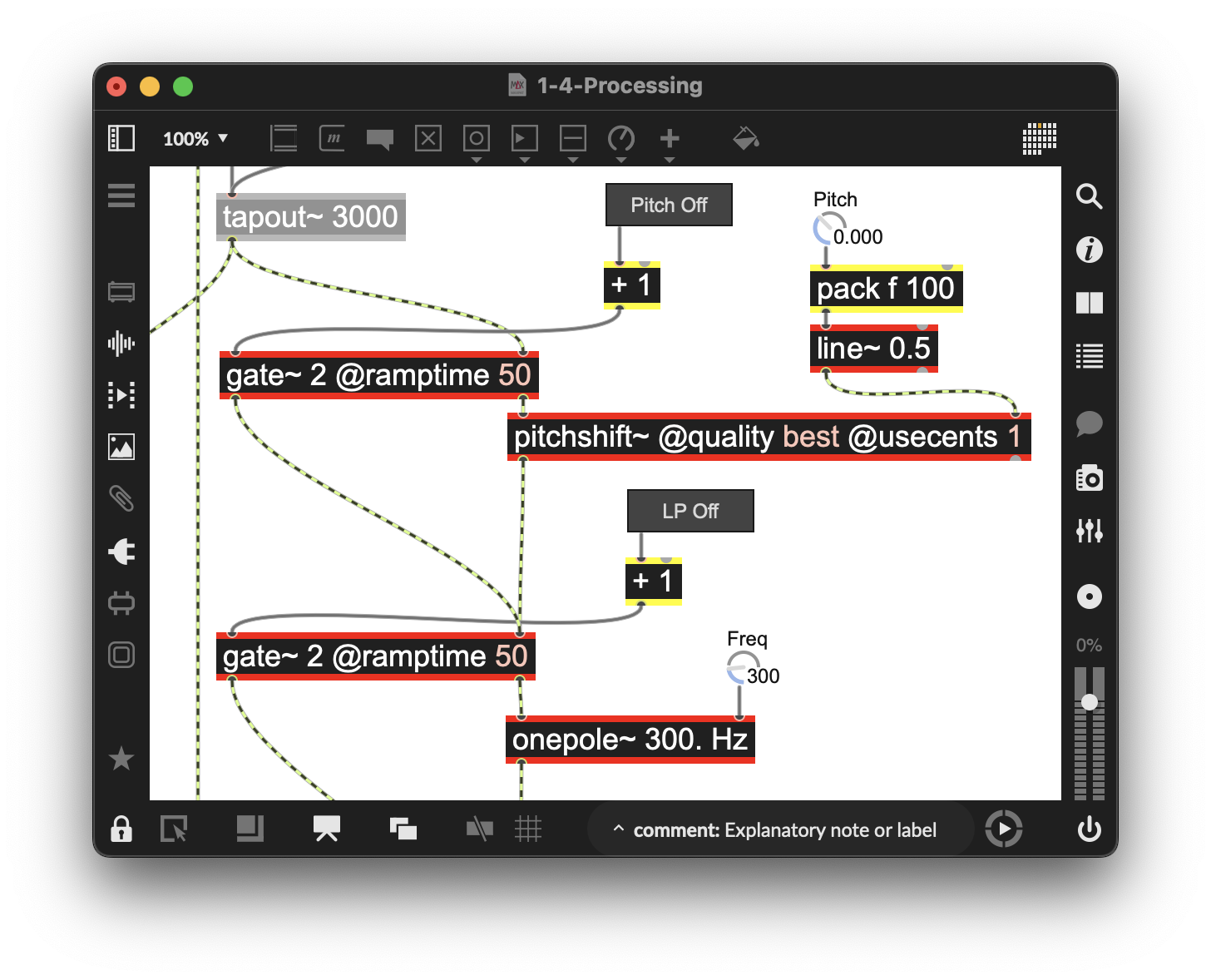
Figure 1-33
For onepole~, we add an initial argument of 300 Hz but make that adjustable with a live.dial named “LP Freq.”
Adding distortion
For our final bit of added signal processing, we will use the MSP tanh~ object to add some nicely rounded “soft clipping” distortion to the loop. This type of distortion that musicians are accustomed to hearing and using is proportional to the input gain of the audio signal; the more the input gain is increased, the greater the distortion. The mathematical tanh() function neatly models the type of distortion associated with the physics of vacuum tubes—when you increase the input signal level to the tanh~ object, it is as if an analog signal is being pushed towards its maximum value. The more it approaches the maximum, the more it distorts and acts like saturation (which is frequently described as sounding a lot warmer and more natural than digital clipping).
As we have done before, we are using a gate 2 @ramptime 50 object for signal routing and a live.text object/+1 pair as a UI and switch (setting Distortion On/Off for the name using the Inspector, and initial enable of 0.). We’ve also added a labeled live.dial object and a *~ signal multiplier object that “goes to 11” thanks to range setting using the Inspector) to control the amount of distortion/clipping we add to the signal. Here is what the final result of the patching looks like:
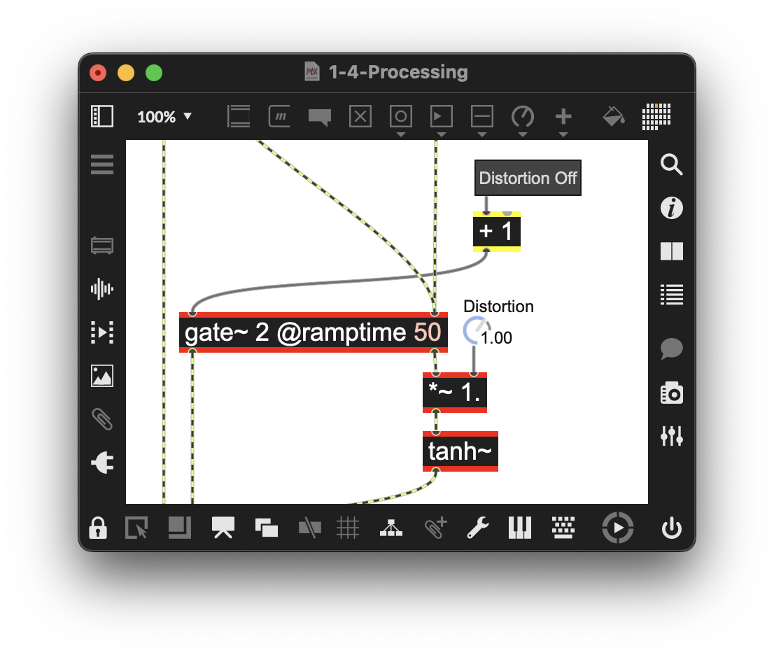
Figure 1-34
More Effects
As always with Max, you can add processing effects both in the loop and to the audio that bypasses the loop, creating a patcher as complex as you might desire.
Creating a Performance UI in Max
(Example Patcher: 1-5-Performance-UI)
Now that we have a functioning looper, it would be beneficial to modify our patcher so that only the parts we are controlling are clearly displayed, making them easier to use during performances. Additionally, we can view this as a way to design a user interface for a Max for Live plug-in in the upcoming chapters.
So far, we have arranged Max objects in our patcher, as we program, in a way governed by the flow of data and audio—rather than in a way that gathers all of our UI objects and arranges them in an orderly and meaningfully visible fashion governed by the demands of a live performance. To create that order, we will use Max’s Presentation Mode, which lets you arrange and resize user interface objects in your patcher independently of their functional position and size in Patching Mode. The Presentation Mode is a separate view from the Patching Mode we’ve been working in until now. Each mode has its advantages, and you can easily toggle back and forth between patching and presentation modes while you work, as well as lock/unlock the patcher window in each mode to switch between editing and running the patch. Presentation Mode, as the name suggests, allows you to create (“present”) only what is needed to perform with, and you can also set your Max patcher to open in Presentation mode automatically when your patch is finished and ready to go.
Here is what Presentation Mode will look like when we’re done patching:
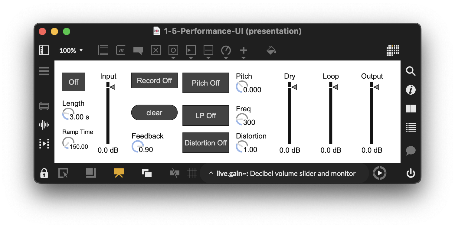
Figure 1-35
We will start with our Max patcher, and begin by selecting only the objects in our patcher that we will want to see in our user interface part (Presentation Mode) of the patcher, and “adding them” to the Presentation Mode. To do this: while in patching mode, select any object you wish to add and select “Add to Presentation…” from the Max Object menu. When you do this, the selected object(s) will be surrounded by a salmon-colored border in the patcher window. Here’s what the final patcher should look like in patching mode:
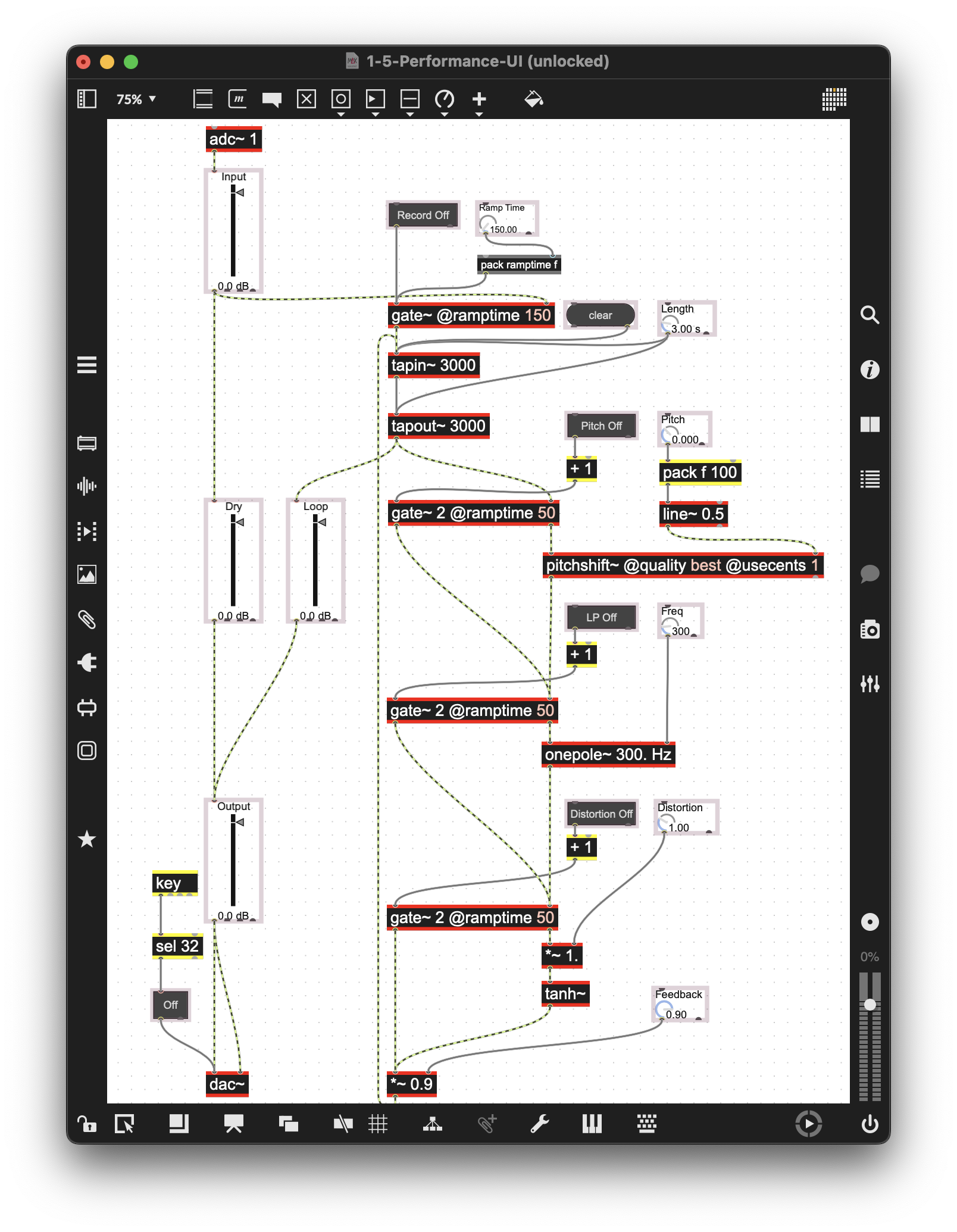
Figure 1-36
To view Presentation Mode, click on the Presentation/Patching Mode icon highlighted in the image below to toggle between Patching and Presentation.
Figure 1-37
You will now only see the objects you have added to Presentation Mode. It might be a mess at first. Arrange these objects to create your user interface. Moving things around doesn’t change their location in patching mode, allowing you the freedom to be creative with the layout.
If you would like to view both patching and presentation modes simultaneously, you can use the Patcher Windows (double rectangles, icon next to the Presentation/Patching Mode icon) to create multiple views of the patcher you are working on, including simultaneous Presentation/Patching views, as shown below.
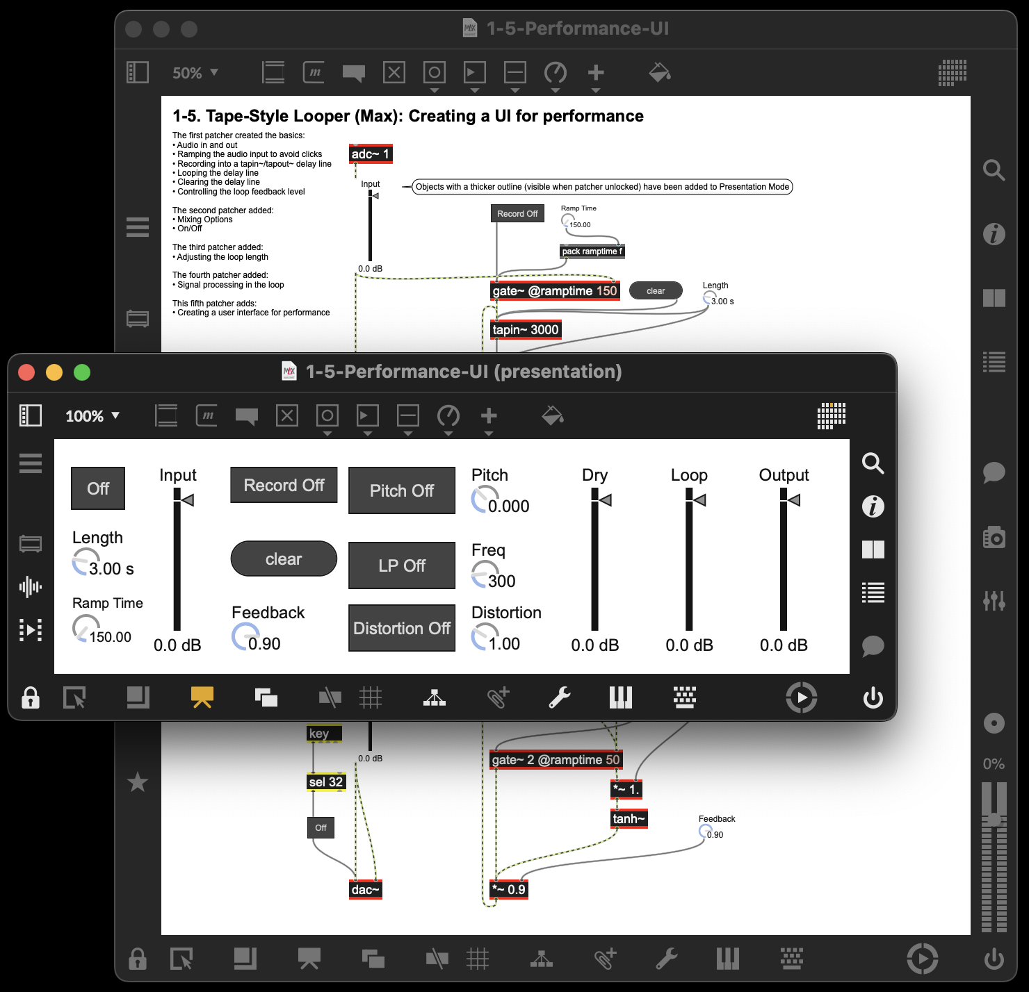
Figure 1-38
To set your Max patcher to open in Presentation mode, use the Patcher Inspector by selecting Inspector Window from the Max View menu (be sure the patcher itself is selected, not an individual object), where you can tell the patcher to “Open in Presentation,” as well as set the size attributes and location for it to open with, and more.
Save and close your patcher; you’re now ready to loop in Presentation mode as soon as you open it.
Conclusion
For this chapter, we have developed a tape-style looper based on the concept of a predetermined, fixed tape-loop length. We also explored methods for processing the audio after it has been recorded in the loop. These processes used within the loop—gates with gate~, pitch with pitchshift~, lowpass with onepole~, and distortion with tanh~—can be repurposed in future loopers, or for building ways to affect sound outside of the loop as well. Nearly everything we’ve developed can be transferred to other types of projects. One key aspect of learning Max is recognizing that everything can be repurposed for other applications.