Chapter 5 — Tape-Style Looper (rnbo~)
rnbo~ Introductions.
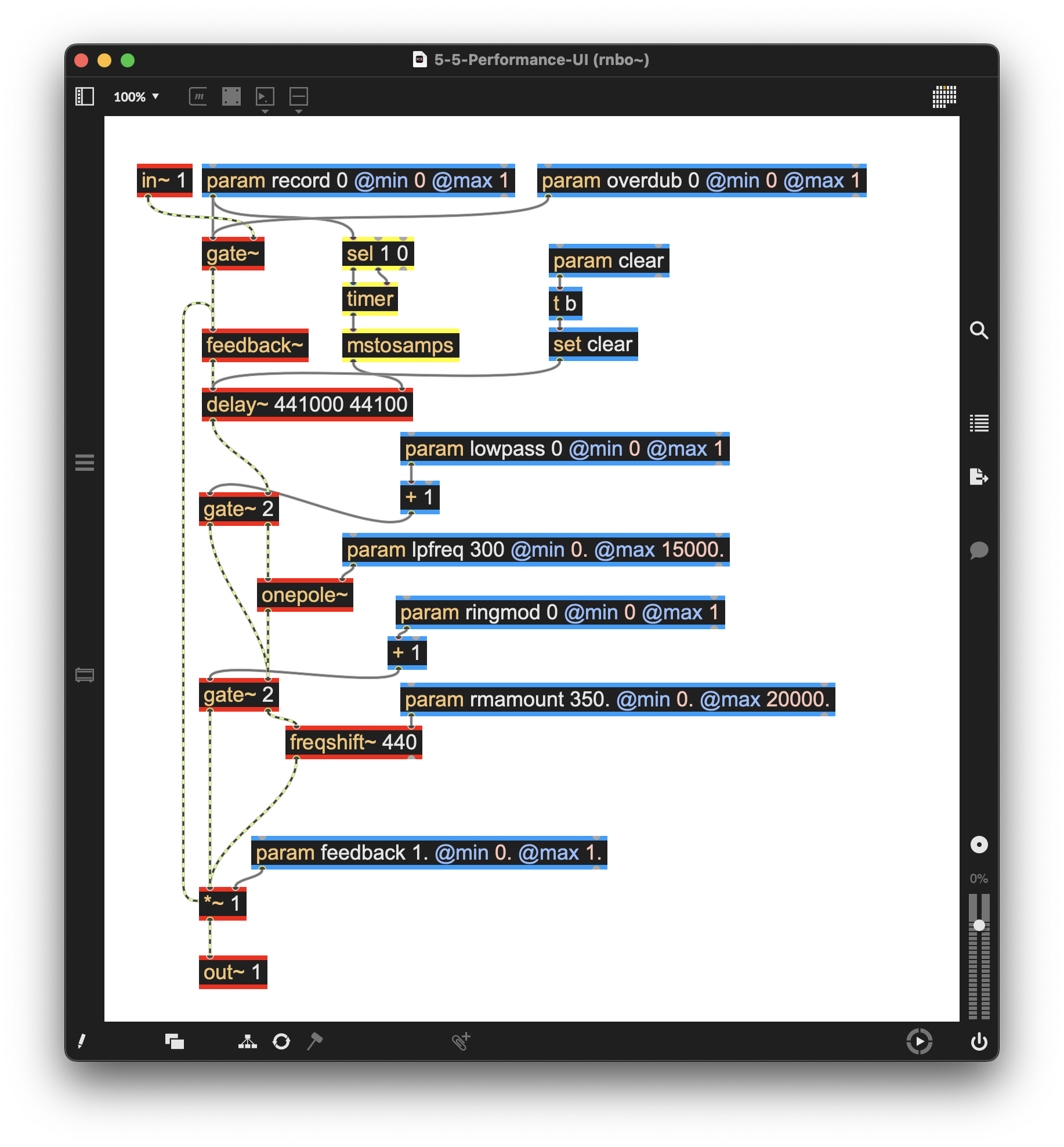
Figure 5-01
One of the goals of this book is to investigate the development of several kinds of loopers in the Max programming environment, and to do so in several forms using different tools available to us as Max users. In this chapter, we will build a tape-style looper using Max’s RNBO object (rnbo~) and its programming environment.
Similar to the Gen environment we worked with in the previous chapter, RNBO is a visual programming environment that allows you to create patchers inside a rnbo~ object. You add a rnbo~ object to your Max patcher just as you would any other Max object, double-click on the object to open it, and add rnbo~ operators and connect them just as you do in the Max and gen~ environments.
What makes RNBO unique is the ability to export a patcher created inside of the rnbo~ objects to several “targets.” At the time of this writing, those targets include:
- VST3 plugins for Macintosh and Windows
- Audio Unit plugins for Mac
- C++ and Web Assembly code
- Raspberry Pi applications
- MSP external objects
RNBO is a visual programming environment that is a paid add-on to Max. However, even if you have not yet purchased an RNBO license, you can try out the patchers we will create in the following chapters for free in demo mode as long as your copy of Max is authorized and you are signed in. If you are using a copy of Max that comes with the Ableton Live Suite, you must sign in manually: select “User Account and Licenses” under the Help menu (you’ll need to do this even if you are using Max in demo mode).
After signing in and authorizing, select “Show Package Manager” under the File menu and navigate to the RNBO package. Select and install it, RNBO will then be fully functional in demo mode, except that you cannot save your work. (Note that you also cannot copy and paste the code elsewhere to save it, either.) It is feasible that you could build a VST plugin and export it in demo mode, but then your patcher would be gone when you close Max.
This chapter assumes greater knowledge of Max than the previous chapters, but works sequentially in a way that unpacks the elements of the rnbo~ patcher into understandable sections for those less experienced.
After you have installed the package, open a new patcher window and add a rnbo~ object (just as we did with our first gen~ patcher and then double-click on the rnbo~ object to open the RNBO patcher window. This new patcher window looks similar to other Max patchers, but you will notice the addition of a page and arrow icon on the right-hand sidebar. Click on this icon to display the Export Sidebar.
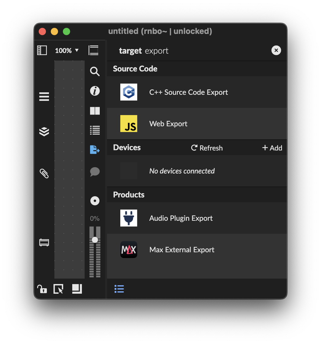
Figure 5-02
This is where we will export our patcher to a target. But first, we’ll need to create the RNBO patcher.
The Basics
(Example Patcher: 5-1-Basics)
We’ll start by building another tape-style looper using RNBO to help you get used to working within the RNBO patching environment.
Although RNBO objects very closely mimic their MSP and gen~ counterparts, there are a few differences in the environments (many of these have to do with changes necessary to support export to the many RNBO targets). You’ll recall that our first tape-style looper patch used the MSP tapin~ and tapout~ objects. At the time of this writing, the tapin~/tapout~ pair of objects is not supported in rnbo~ (it’s currently not possible to implement the internal mechanisms that tapin~/tapout~ takes use in MSP to manage feedback loops). We’re going to use a delay/feedback loop in our patcher: the feedback~ object in RNBO will introduce a single sample of delay in the loop, preventing it from spinning out of control. For the most part, Max has built-in protocols to avoid such out-of-control feedback loops. For example, if you tried connecting at delay~ to itself in rnbo~ without the feedback~, it just would not allow it.
Here is what the first looper patcher looks like:
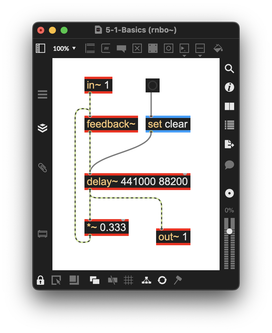
Figure 5-03
With these seven objects, we have created a working feedback loop that will form the basis of this patcher. Your experience with Max means it’s pretty easy to see what’s happening; in~ and out~ objects handle audio input and output from the rnbo~ patcher.
The feedback~ object adds a single sample of delay, allowing us to create a feedback loop using our delay~ object. The delay~ object includes two arguments that set (in samples) the maximum delay time available and the initial (default) amount of delay to use.
You’ll also notice a new object you haven’t seen before—a set object with an argument of clear. We’re using this object because the RNBO environment (unlike MSP and Gen) only accepts bang messages or floating-point numbers, no symbol-based messages. To implement sending a clear message to the delay~ object, we use the set object with an argument that describes the message we want to set, and then we use a button here that sends a bang message.
Finally, we’ve added a *~ (multiply inputs) object that we use to lower the delayed signal's amplitude before sending it back into the feedback~ object to prevent any volume explosions.
This loop is fully functional and will continue looping until you clear it, at which time it will start looping again. Next, we will add some controls to the looper.
Mixing options
(Example Patcher: 5-2-Mixing)
In this iteration of our rnbo~ patcher, we have added a gate~ object and three param objects. These objects work in the same way as their Gen counterparts. The param allows us to access messages from the rnbo~ patcher’s parent patch with arguments that set the message we will use to access this particular param object (e.g., param record and param feedback). A gate~ object works just as it does in the MSP and Gen worlds. In this patcher, the gate~ works in conjunction with the param record object to open the gate~ object, enabling audio input to the looper and allowing us to decide when and what to record.
You’ll also notice that we can use arguments to set the initial state of our objects, and attributes @min and @max to set the range of numbers we want to work with. In this patcher, the param record object’s default setting is off/0, with a range of 0 to 1, and the param feedback object’s default is set to 1. with a specified range of 0. to 1.0. In this case, we want a 1 to open and a 0 to close the gate~.
The next param is named “clear.” This param will send a bang message to the set clear object. We do not have an argument in it, as when we send the message “reset,” it triggers a 0 out of the param, which the trigger (t) then uses to send a bang to the set clear.
The last param we added controls the volume level of the feedback loop. We limit this to a maximum of 1, allowing you to overdub while retaining 100% of the loop volume.
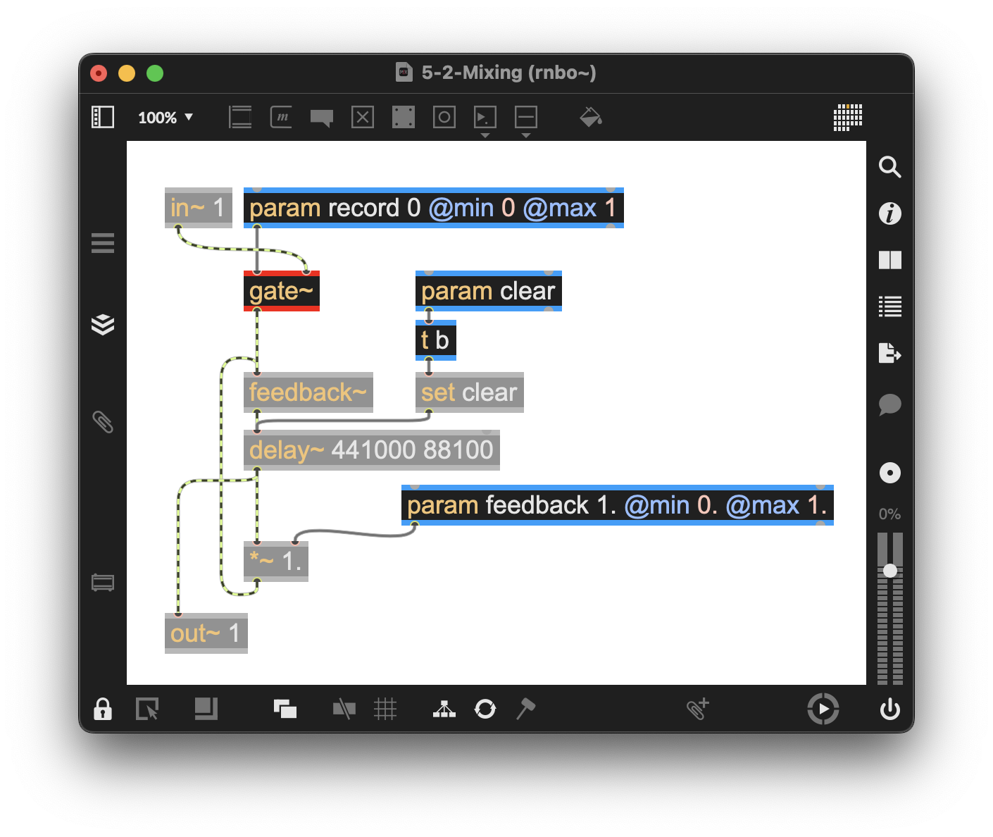
Figure 5-04
The rnbo~ patcher accesses these param functions by sending messages from the parent Max patcher. The reset message is a generic message for all RNBO patchers that will reset all objects to their default state. The second (record $1) uses the replaceable argument $1 to send a 0 or 1 to the param record 0 @min 0 @max 1 object, which opens or closes the gate~ to enable audio input to the loop. The param feedback 1. @min 0. @max 1. allows us to send a feedback $1 message to set the amount of signal preserved in the feedback loop; numbers less than one will create a fade-out effect.
Now we’ll turn to adding UI objects in the parent patch. We have also added a few elements for mixing our dry audio and looped audio, including an on/off switch with the spacebar, and a “reset” message to initialize our Live UI objects to their default state.
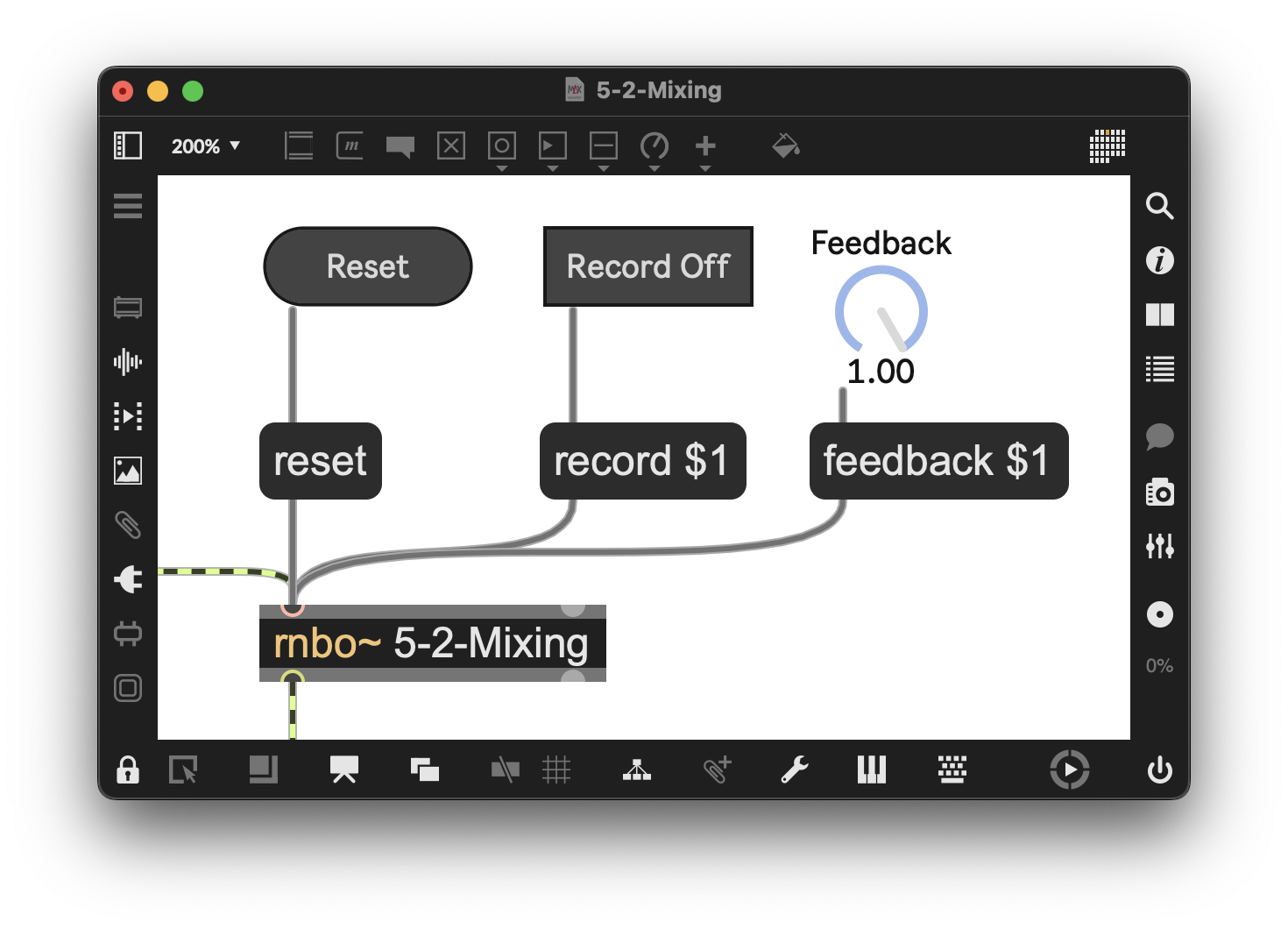
Figure 5-05
We have also added a few elements for mixing our dry audio and looped audio, an on/off switch that uses the spacebar, and have the “reset” message to initialize our Live UI objects to their default state (set in the Inspector with “Initial Enable) with a trigger (t) “init.”
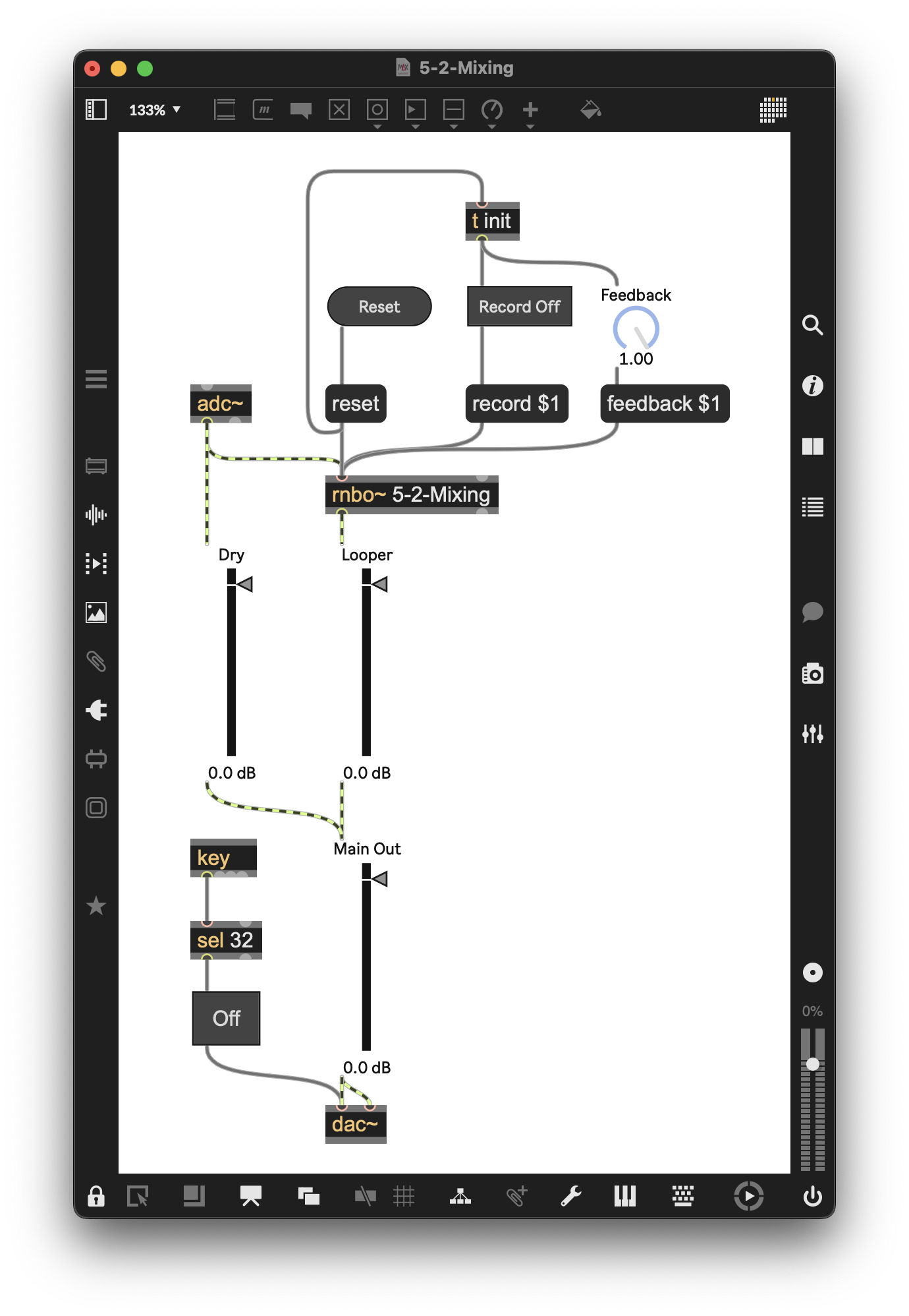
Figure 5-06
Setting the Length (Example Patcher: 5-3-Length)
(Example Patcher: 5-3-Length)
We have set the delay~ to a maximum available duration with our first argument. Here we have a difference from our tapin~/tapout~ pair, in that we can set the duration with a timer object and not clear the memory. We take the output of the timer (in milliseconds) and use a mstosamps (milliseconds-to-samples) object to convert the timer object's milliseconds into samples. For this patcher, we create a multipurpose use of our record button. When we select record outside rnbo~ (1) in addition to recording, it starts a timer. When we are done recording (0), it
- Ends the timer
- Outputs that value (milliseconds)
- Converts the timer objects' milliseconds to samples and;
- Uses that to set the length of the delay~ (the loop).
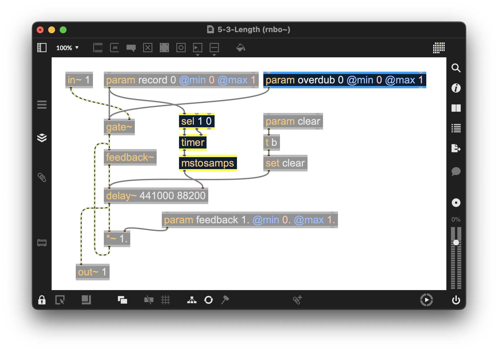
Figure 5-07
Since we are using our record param to set the length, we need to add an overdub param to open the gate~ without retriggering the timer to avoid changing the loop's length every time we overdub.
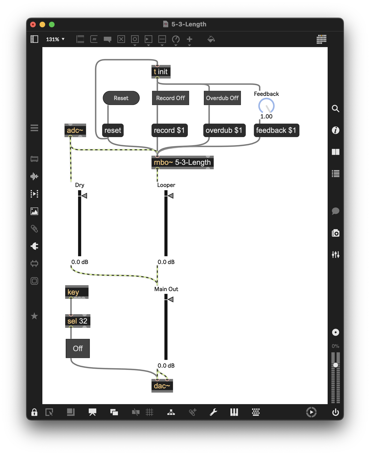
Figure 5-08
Processing Audio in the Loop (Example Patcher: 5-4-Processing)
(Example Patcher: 5-4-Processing)
This section is very similar to the earlier chapter on processing in the loop with patcher 1-4-Processing. We will take a signal into a gate~, and then decide which outlet it goes to: the first outlet bypasses the audio effect (processing), and the second outlet sends it to the audio effect.
In the image below, you can see audio going into the right inlet of the gate~. The param for lowpass tells the gate~ to either send it to the left outlet, bypassing the processing, or the right outlet with the onepole~ to lowpass the audio. Whichever is selected goes to the next gate, which repeats the process. In addition to the param that chooses to bypass or process the signal, we have also added a param to set the value of the lowpass filter.
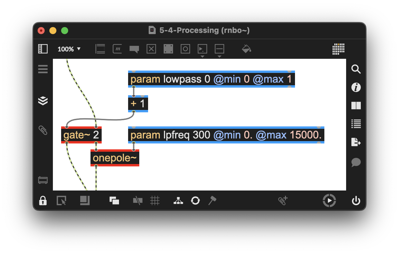
Figure 5-09
For this example, the next gate goes into a freqshift~, a type of ring modulator. (Remember, all these processing effects can be repurposed wherever desired.) We have a gate~ with param to bypass or process, as well as another param to set the freqshift~ frequency.
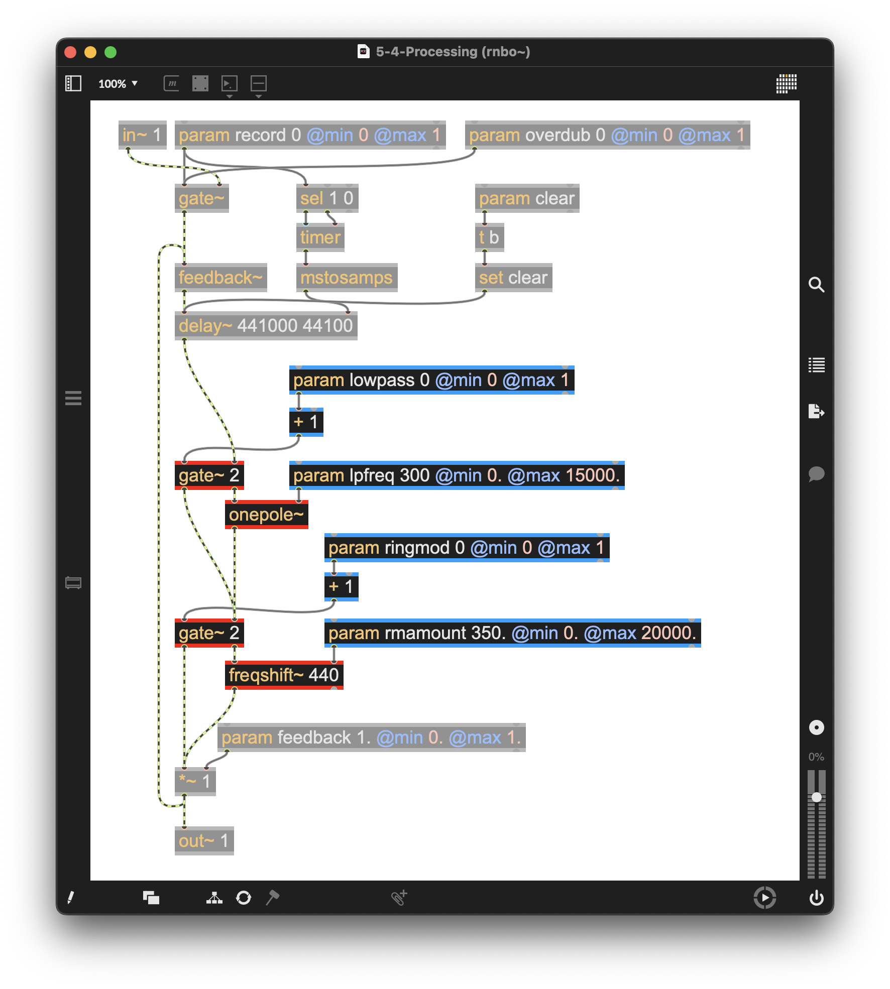
Figure 5-10
And these new param are accessed via additional messages from the parent patch what contains the rnbo~ object:
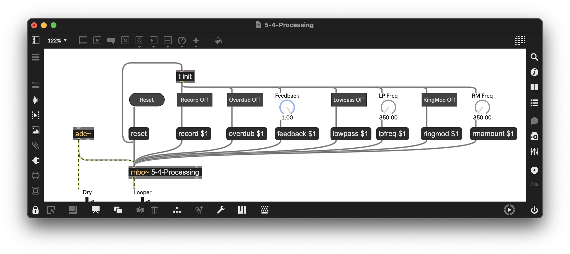
Figure 5-11
Creating a UI for Performance
(Example Patcher: 5-5-Performance-UI)
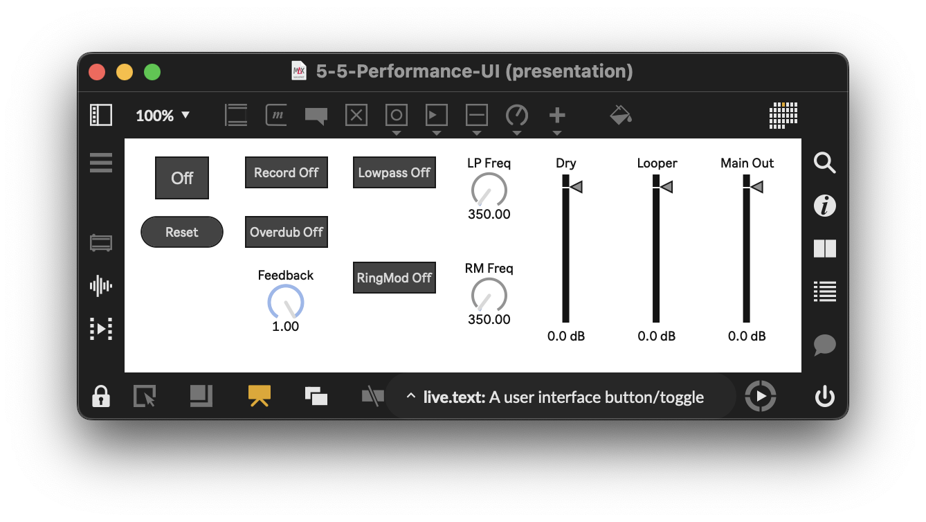
Figure 5-12
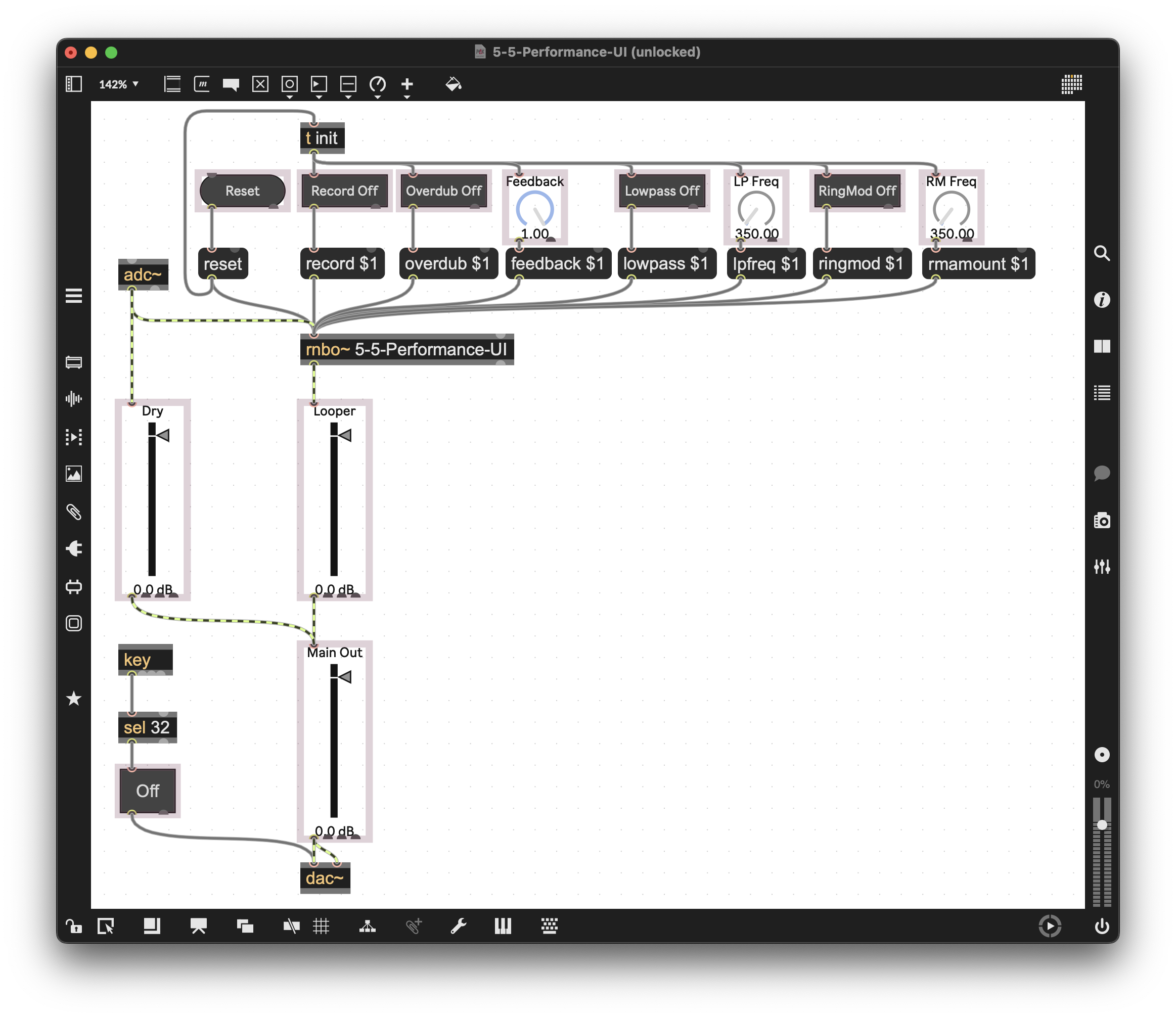
For the final UI, we have added our Live UI objects into Presentation Mode and organized them in a helpful manner. You can move them around as you desire. As before, the outline around the objects shows that they are added to Presentation Mode.