Chapter 3 — Basic Looper (gen~)
Introduction to the gen~ Environment in Max
The gen~ object provides a powerful and efficient environment for building audio loopers within Max. The gen~ object allows you to program visually, similar to how you work in Max. However, it compiles your patching within the gen~ patcher on the fly and runs it efficiently as C code. This combination provides the ease and familiarity of a visual programming environment alongside the performance of text-based code.
There are some key differences between working in Max and using the gen~ object for patching.
- Everything in gen~ operates on a sample-by-sample basis
- gen~ utilizes a smaller set of objects, known as operators
- The gen~ environment does not support message types
While this chapter presumes a greater working knowledge of Max than previous chapters, we’ll be working through patches sequentially in a way that breaks down the elements of a gen~ patcher into bite-sized sections for the less experienced. Note: for Max for Live users (the version of Max included with Ableton Live): You will not be able to edit gen~ patchers unless you own a standalone copy of Max.
To start patching in the Gen environment, add a gen~ object to your Max patcher just as you would any other Max object.
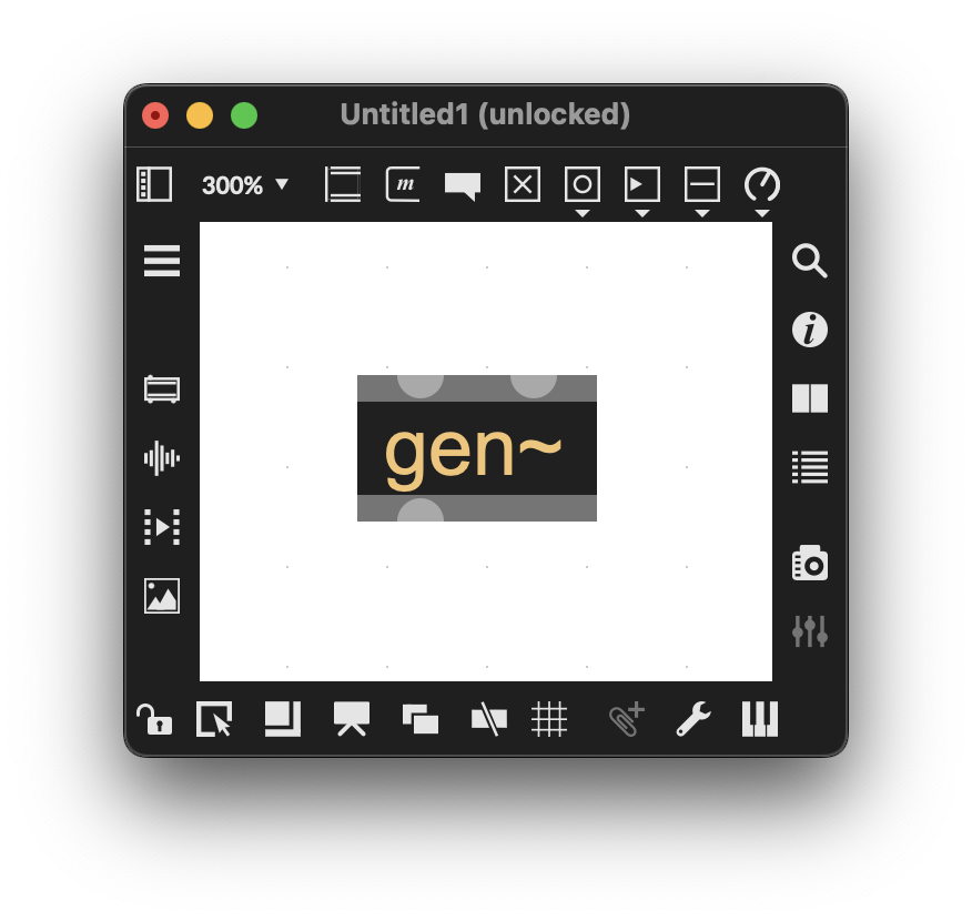
Figure 3-01
Gen objects resemble Max abstractions in that they can be opened by double-clicking on them in a locked patcher, option/alt double-clicking in an unlocked patcher, or sending an “open” message. The initial default version of the object has two inlets and an outlet. What you see when you open it should look something like this:
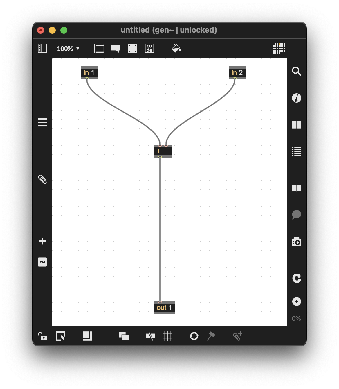
Figure 3-02
The in operators bring signals into the gen~ patcher from Max. You then do the processing work inside the gen~ environment and output the resulting signal via the out operator. Notice that the in and out operators are numbered, allowing for the creation of multiple unique ins and outs.
The gen~ patching environment looks similar to a Max patcher in that we add gen~ operators (each of which has a specific function) to a patcher and connect them together. As we do so, the gen~ patcher compiles itself as we patch. What might appear similar to Max objects, in gen~ are called “operators.” Like Max objects, they represent a specific functionality: they have a task that they do. Unlike Max objects, the functional units of a gen~ patcher can exist as gen~ operators, or work with the GenExpr programming language using the expr and codebox operators, objects, or as GenExpr code. We will focus on operator-based object workflows for this chapter, and we will use the term “operators” to distinguish the contents of a gen~ patcher from Max patchers.
One of the things that beginners to gen~ patching sometimes find daunting is that gen~ does its work one sample at a time, and that there are no messages inside a gen~ object: every bit of data that passes between gen~ operators is a single byte of data and that data can represent audio signals, operators that control the flow of data in a gen~ patcher, and other operators that handle timing. Learning to use gen~ operators involves making sense of the different uses of single-sample operators.
To help you navigate the gen~ environment, we’re going to use a color code similar to the colors used in the Max patchers in the previous chapters’ sample patchers to help keep operators and their functions—for this patcher—more visually apparent. Since we’re working with single-sample operators that pass data at signal rates, the labeling will be slightly different.
Color coding framework for this chapter:
Red operators will be used to indicate audio in a patcher. Everything is data in gen~, but we will use the term audio to refer to data that is being used for audio. Color coding will focus on function, where operators will be used for data as audio, and others for data that is not audio, for example, a selector may have different colors based on its use. Here are some examples of gen~ operators we’ll be using as we create our loopers that will be colored red:
- Audio input to gen~ (the in operator)
- Writing/recording audio, again, as data (the poke operator)
- Operators that store audio in the patcher examples (the data operator)
- Operators that read/play audio (the peek operator)
- Operators that select an audio signal to pass/not pass (the selector operator)
- Audio and signal output (the out operator)
Blue: parameter operators (param). Param operators function as parameters that control what is happening inside a gen~ patcher that can be modified with messages from outside the gen~operator. The first argument of a param is the name of the param, and can be arbitrarily named (we have found it best to use names that are short and meaningfully describe the functions controlled. The param names used in this patcher:
- record
- play
- latcher
- resetcounter
Yellow operators indicate timing-related operators in this patcher, which control when data is allowed to pass or how long a portion of the patcher takes to do its work. For example:
- A counter operator controls when a poke operator writes audio data (recording) and when a peek operator reads and outputs audio (playing).
- A latch operator can be used to sample and hold data. In our sample patcher, we’ll use it to set the maximum of the playback counter (which corresponds to the loop length in the example patcher we’ll create).
- The !- operator is used to stop/reset playback in conjunction with the play param and counter operators.
- A selector operator is used to send the output of a counter operator to a poke, operator, controlling where to send audio data to write/record when the looper is in record mode.
Gray: As with the Max patching examples, operators we have added to the previous iteration of a patcher are in gray to help keep focus on new operators and sections of our patcher.
Record, Play, Stop, and Reset in a gen~ Looper
(Example Patcher: 3-1-Record-Play)
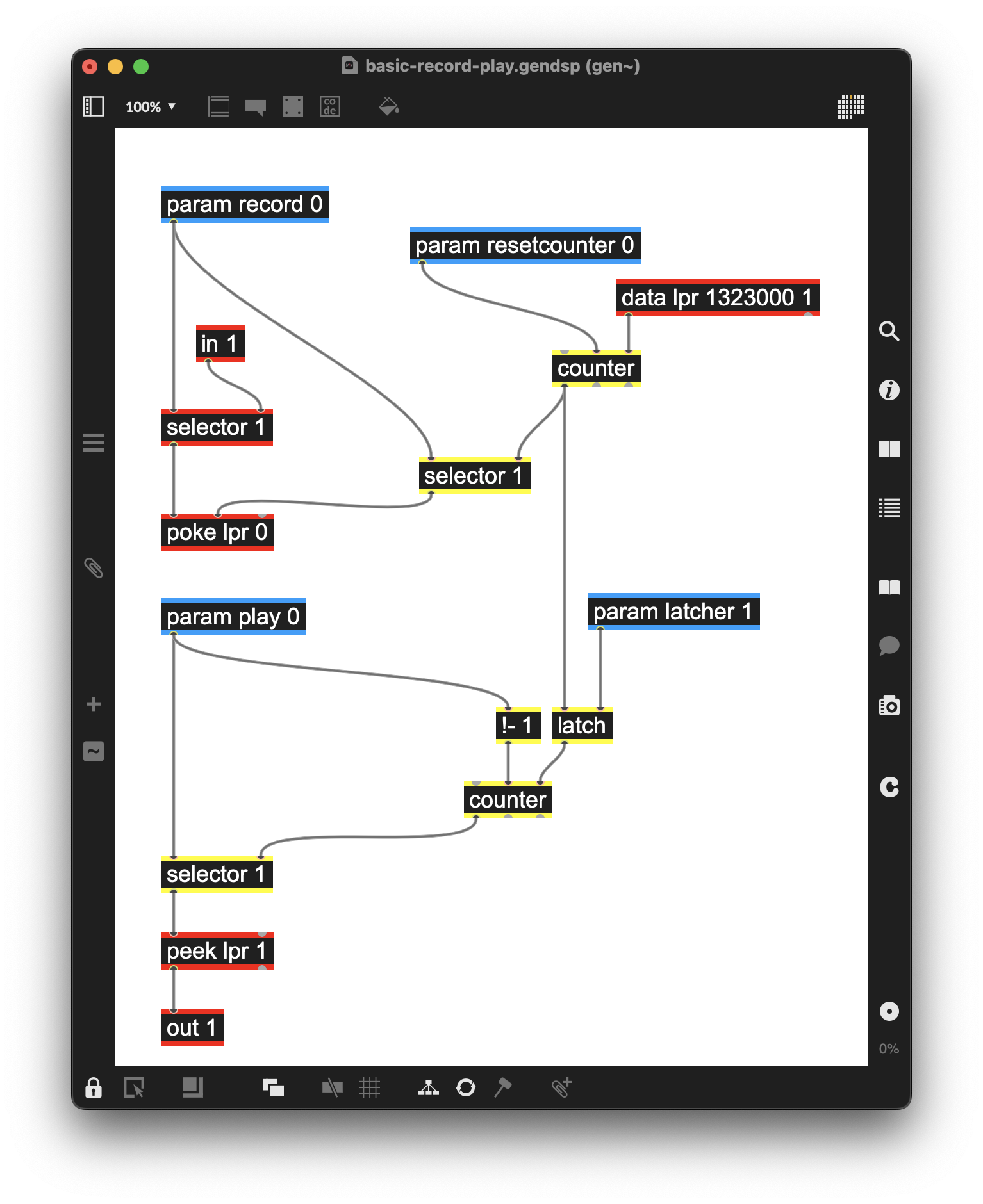
Figure 3-03
For our very first bit of patching in the gen~ environment, we’re going to focus on the basics of looping: recording, playing, stopping/pausing, and resetting.
The first step is to add a gen~ to your Max patcher just as you would any other Max object.
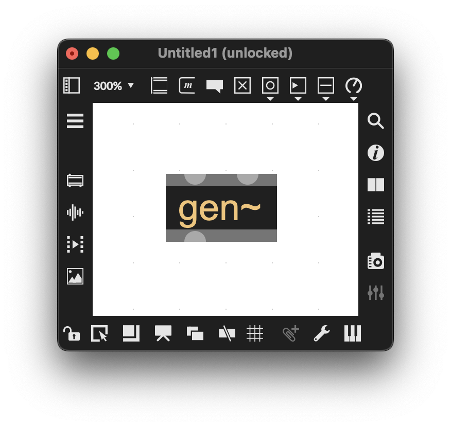
Figure 3-04
Double-click on the gen~ object to reveal the internals of the patcher. You’ll see the default two in operators, an out operator, and a plus (+) operator that adds the two inputs together one sample at a time:
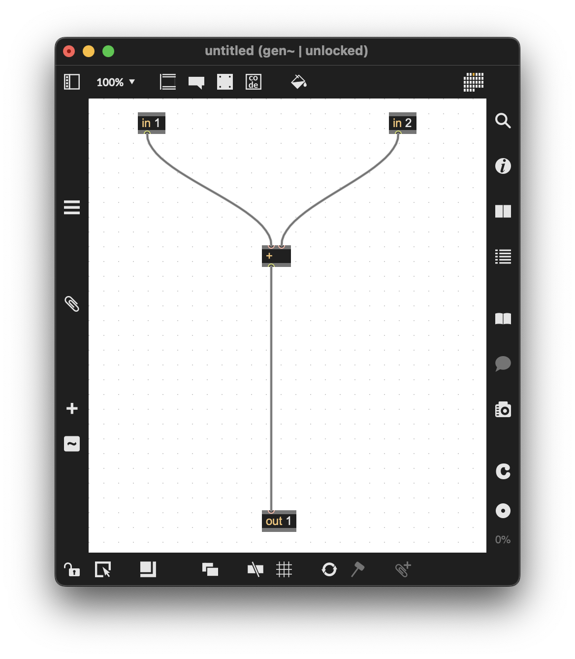
Figure 3-05
We’ll begin by removing the operators from this patcher that we don’t need. Select and delete everything in the patch except for the in 1 and out 1 operators.
We’ll begin by adding a switch that will let us turn recording on using an operator similar to the gate~ object we’d use in a Max patch: the selector operator. When we add the operator, we’ll add the argument 1 to it to indicate that there will be one input (if you increase the number of the argument, it adds inputs—a selector 2 operator would have two inputs, for example).
Connect the output of the in 1 operator to the right input of the selector 1 operator to route the signal input of our patcher to the gate we’ve created.
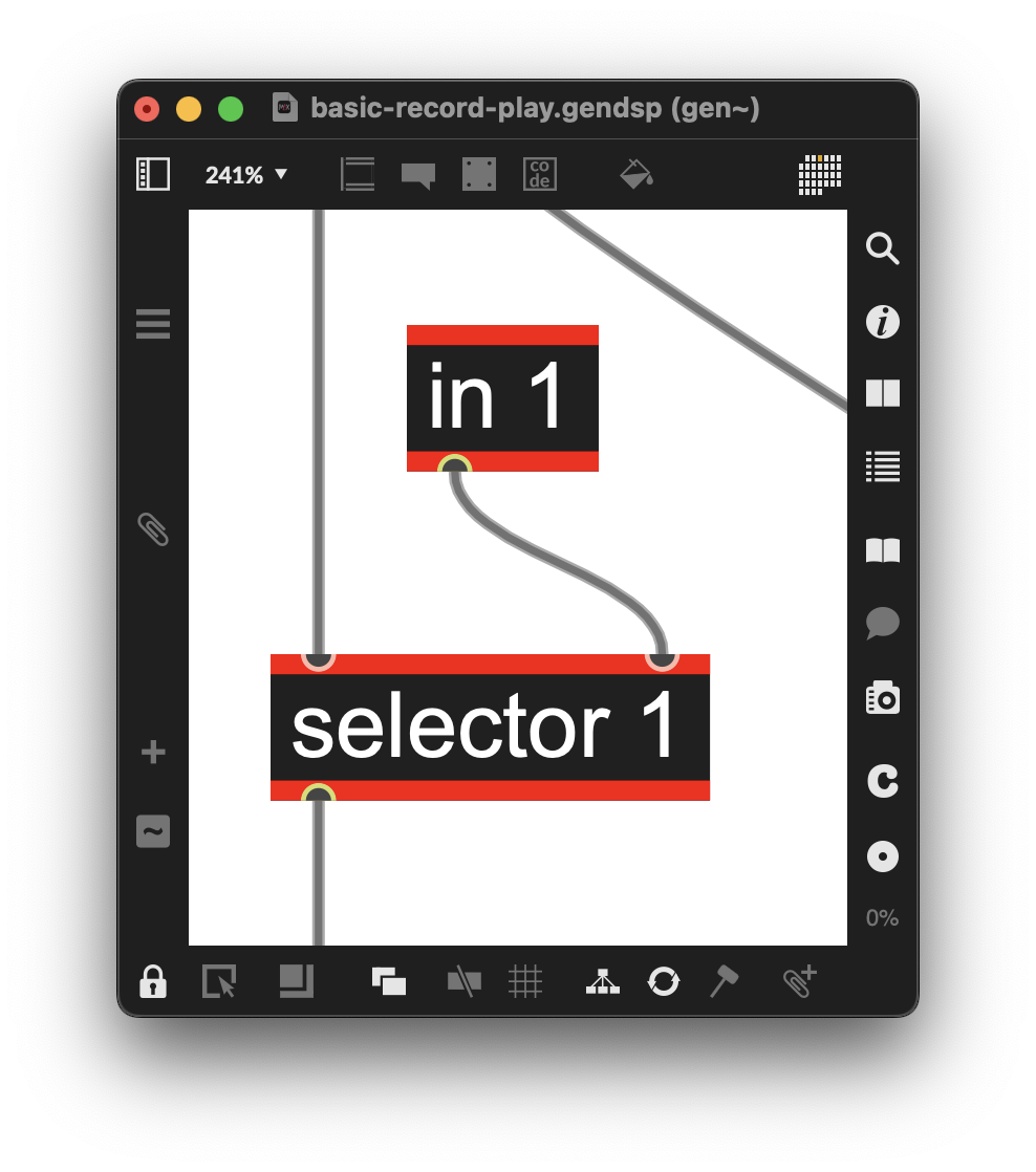
Figure 3-06
One of the differences from the Max environment you’re used to working with is that gen~ does not communicate internally using messages. You can, however, send messages from your Max patcher into the gen~ object by adding a param (parameter) operator to the gen~ patcher. Like the Max gate~ object, the selector operator uses a value of zero to close the gate, and a 1 to pass the input through. Add a param operator with a first argument “record” to specify the message from outside the gen~ object, and a 0 to specify is the default setting for the param (so the gate is “off” by default).
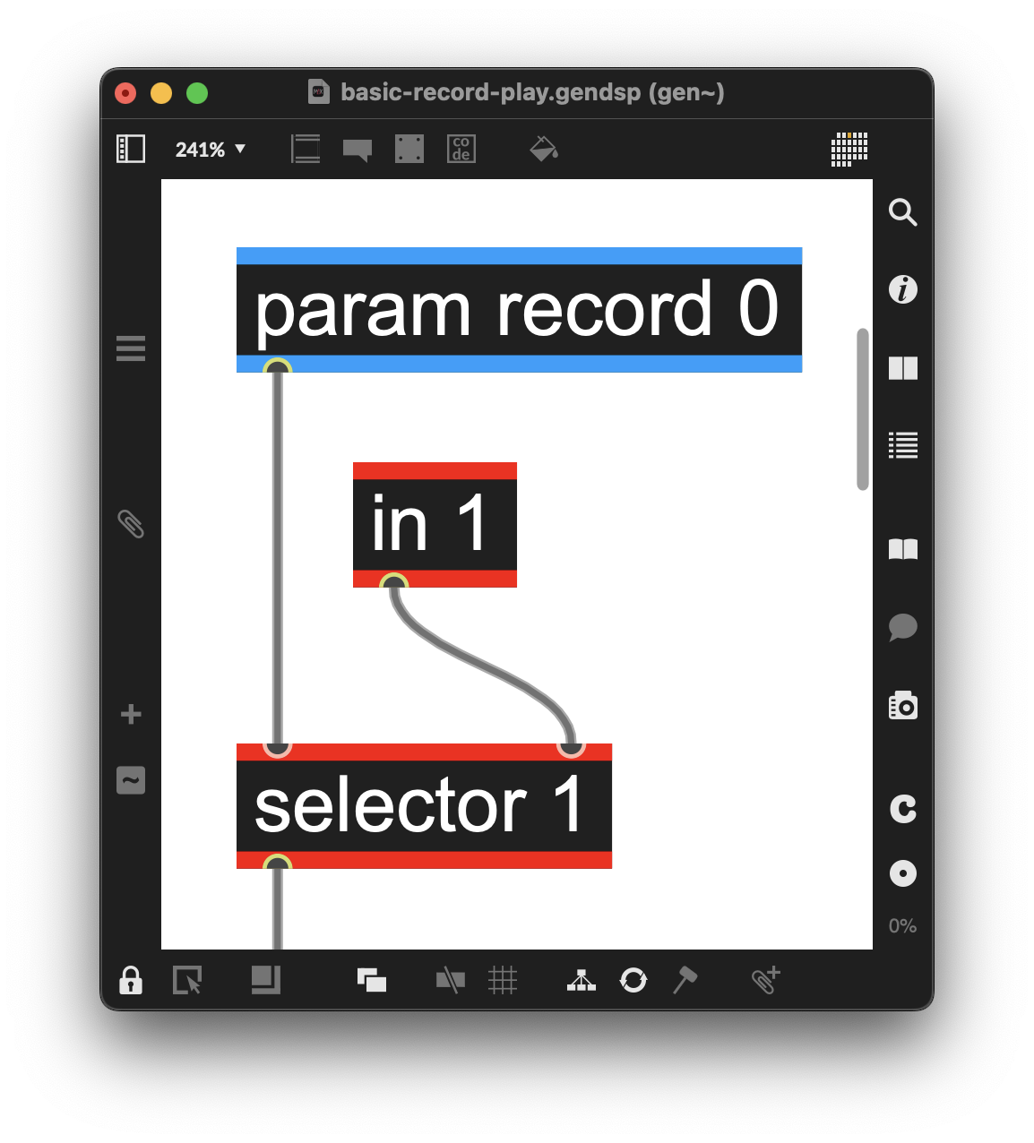
Figure 3-07
In the Max patcher that contains our gen~ object, we’ll enable recording by adding a message box connected to the gen~ object’s inlet that contains the message “record” with a replaceable variable $1 and attaching it to a toggle object. When the toggle sends a 0 or 1, it sets the value of the param operator named “record” inside the gen~ object to that value, opening and closing the selector as desired.
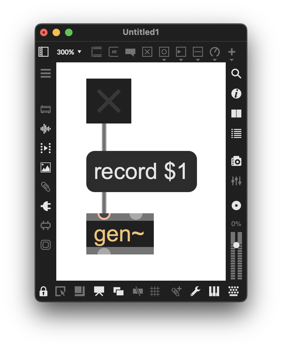
Figure 3-08
Next, we need a source of audio input to our gen~ object. This first inlet of our gen~ will also receive audio input from the Max patcher (where we’re using an adc~ object for input). You’ll notice that both the audio input and the output of the message box are connected to the inlet of the gen~ object: the input to gen~ is smart in that it will sort the named message and audio to their proper destinations inside the gen~ object. We connect the gen~ object’s output to a dac~ object in our patcher.
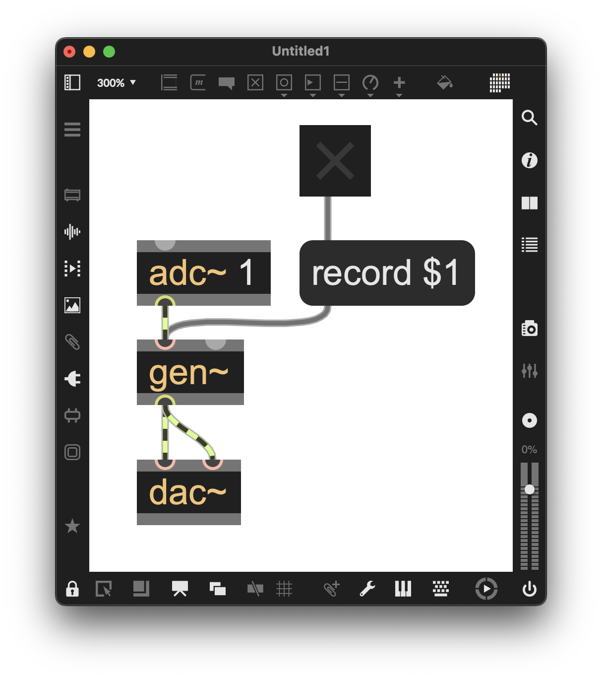
Figure 3-09
It’s time to patch the inside of our gen~ object to set up recording and playback. We’ll need a place to store the audio we read and write, and we’ll use a data operator for that purpose. We’ll add a data operator with three arguments: a name (lpr) for the object, a number that sets the size of the operator in samples (1323000 = 30 secs at 44100 KHz), and the number of channels in our buffer (1).
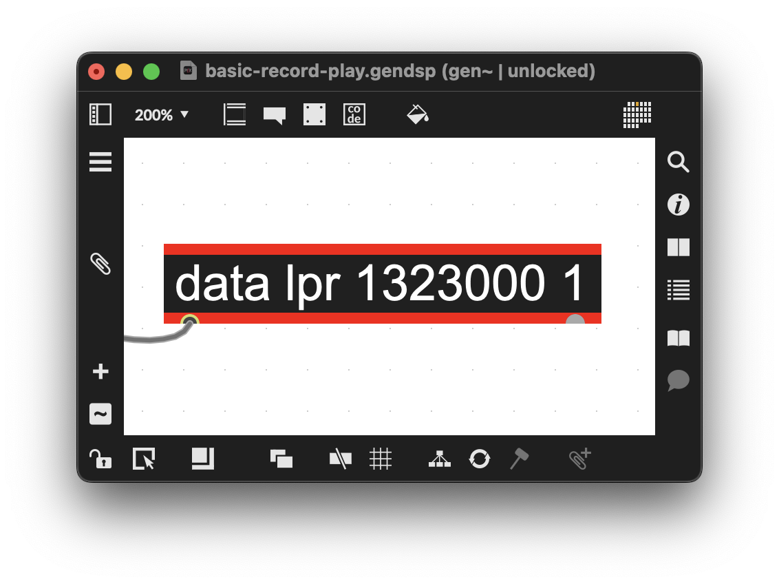
Figure 3-10
We will be using two Gen operators for recording and playback, whose names you may recognize from their Max counterparts: poke to write (record) audio and peek to play (read) the audio. Together, the data, poke, and peek operators work together by sharing a common name “lpr” (like the previously examined trio of record~/buffer~/groove~ examples). For writing/recording audio, we’ll add a poke operator with arguments that specify the name of the data object we’ll write to and an additional argument of “0”, which specifies we will only be using the first channel of audio (channel numbering starts at 0).
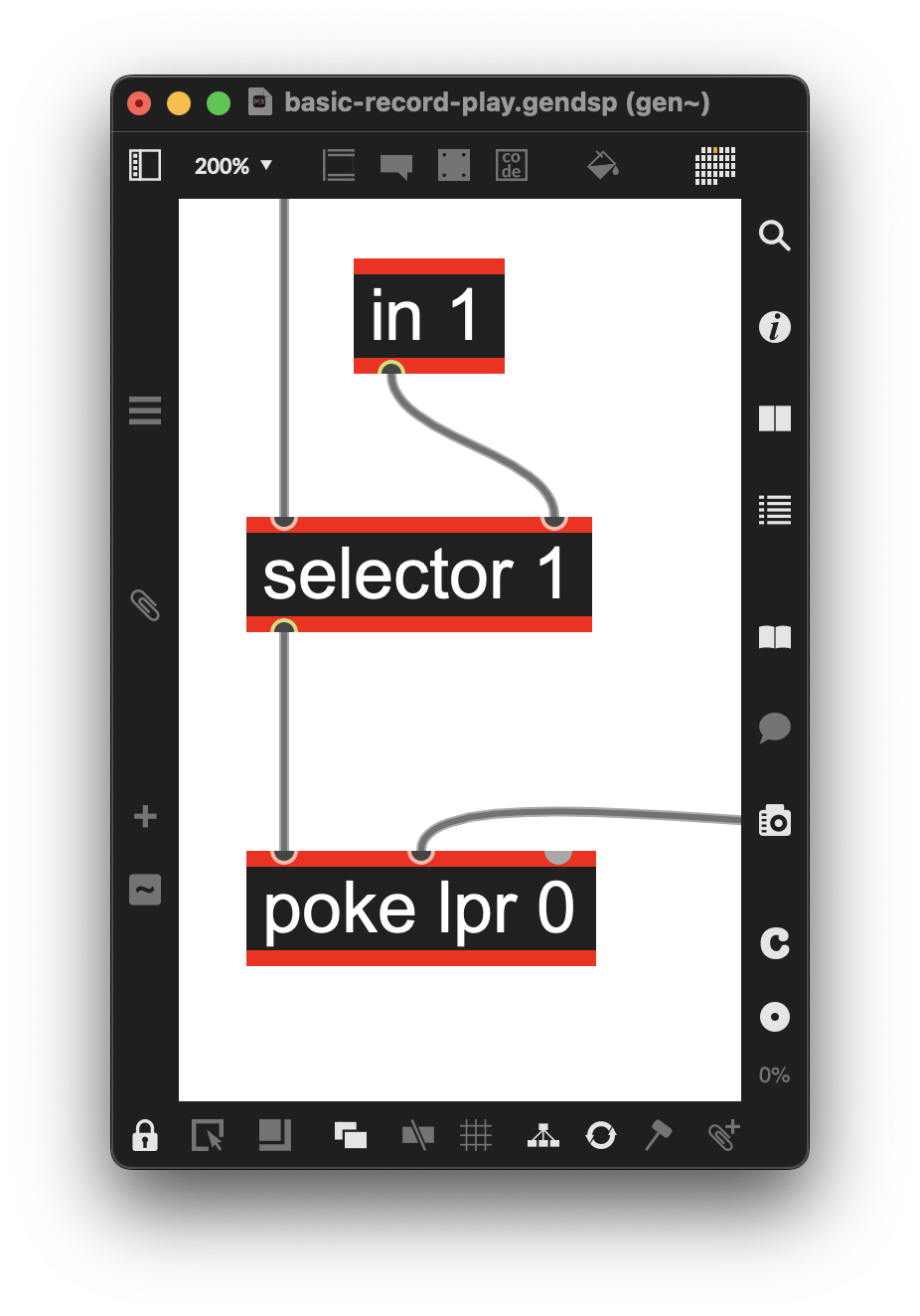
Figure 3-11
For reading/playing, we’ll use a peek operator with arguments that specify a buffer name and channel offset.
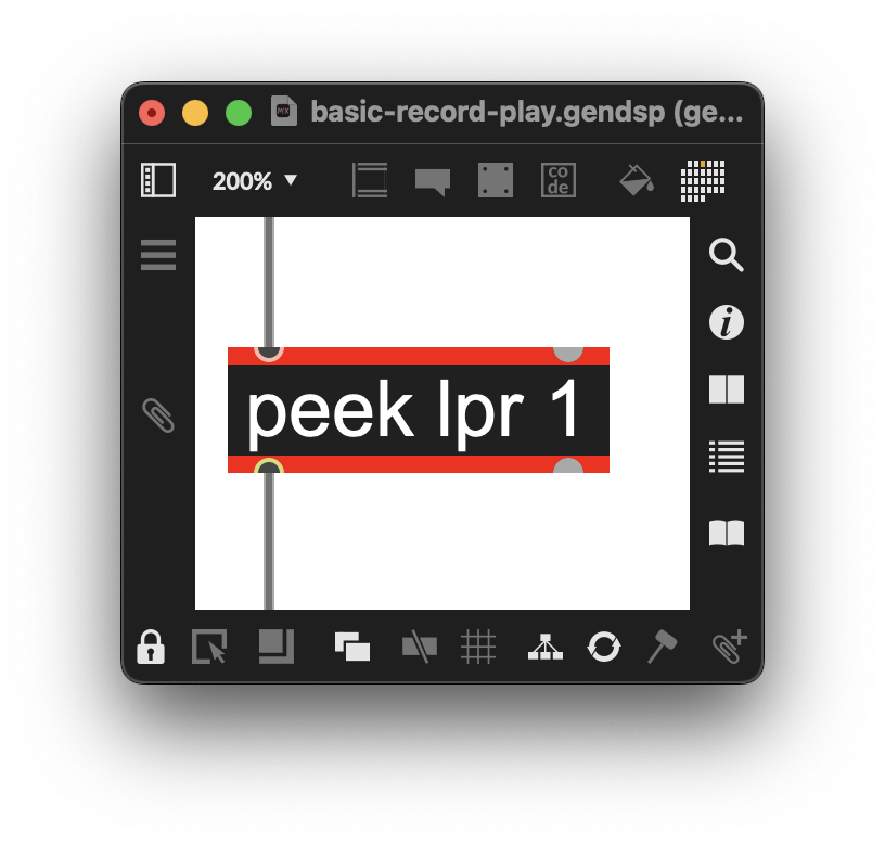
Figure 3-12
Now that we have the recording and playback operators in place, we need a timing mechanism that does two things:
- We need a timing mechanism that lets our trio of data/read/write operators know at what location in time to do all this writing/storing/reading in our buffer.
- We also need to know when in time to do them.
While there are several ways to do this in gen~, we will start with basic combinations of the abovementioned operators using three new operators: counter, latch, and !- (reverse subtraction).
The counter operator is the heart of our timing control patching: it counts through the number of samples in our buffer at a single-sample rate. To set the counter's initial upper limit, we’ll use the fact that the data operator sends the number of samples it contains from its outlet. All we need to do is connect the output of the data operator to the rightmost outlet (the upper limit) of the counter operator.
Whenever we begin our loop, we also want it to start counting from 0. We can do this by adding a named param operator (resetcounter) with an argument of 0 to set the default state (the value of 0 indicates that our counter is always running by default) and connecting its outlet to the middle inlet of the counter operator. Sending the message resetcounter 1 to the gen~ object in the Max patch will automatically reset our counter to 0.
Here’s what our timing patch looks like with its upper limit set and a param object to reset the count:
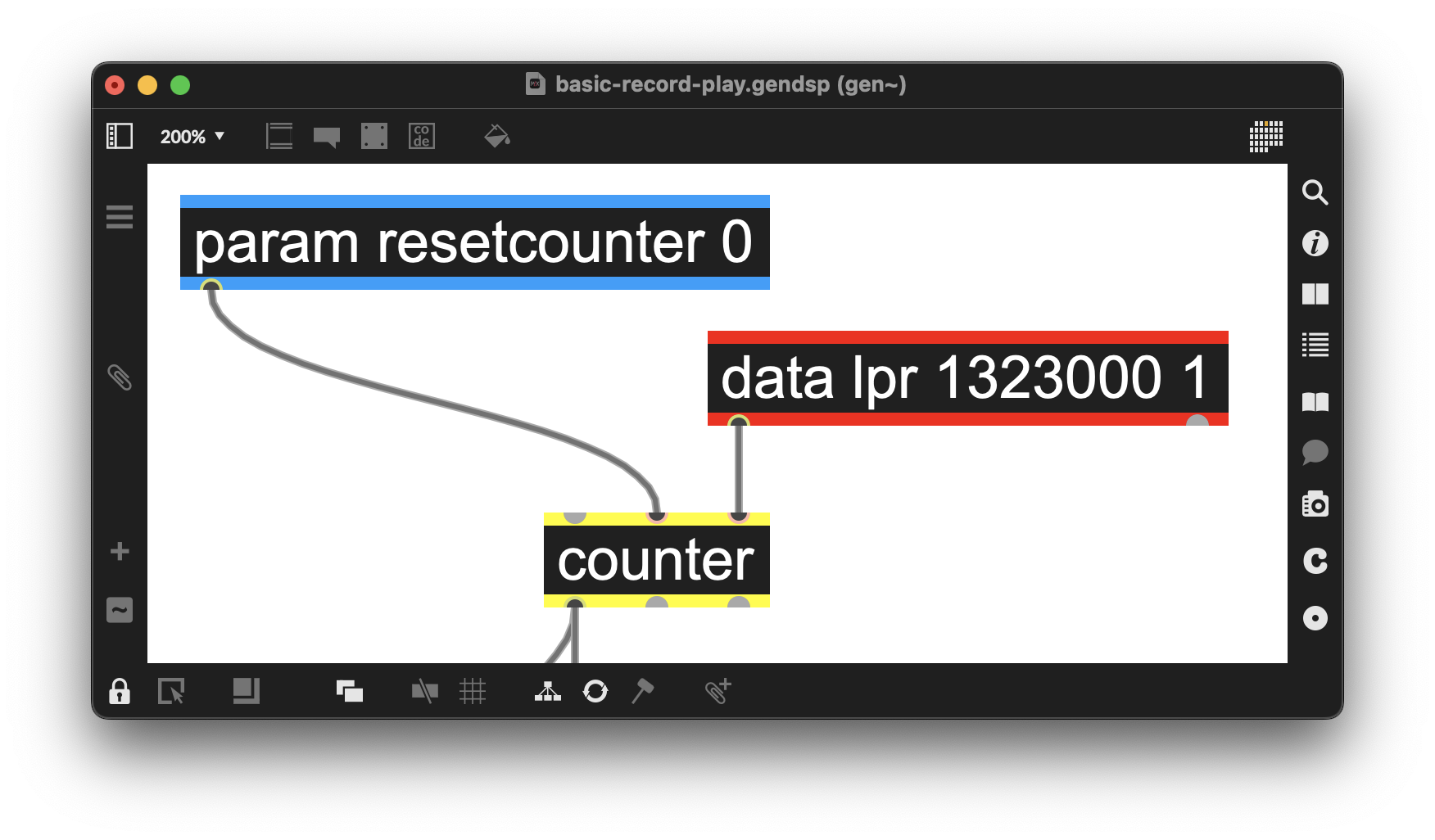
Figure 3-13
The output of our counter is used to set the point where we write (record) audio to the data operator using a poke operator. While that’s happening, we’ll also need to have the counter start running at zero by setting the resetcounter param to 0, indicating the location in the data operator to store the audio. To do that, we’ll add a param record 0 operator that will let us enable/disable recording by sending 0 or 1 from our MSP patcher and use the param object’s operator together with a selector operator that will be opened or closed by the param record 0 operator’s output, letting in audio. We also connected the param record 0 operator’s output to the left input of the selector operator we’re using to enable/disable writing to the data operator, letting in the count. This way, we can use the record button in our MSP patch to handle two tasks simultaneously. Here’s what happens when we toggle a record button in the parent MSP patch:
- Everything in the gen~ object is reset using the generic reset message, which enables audio input (via the selector and the param record 1 operators)
- The counter is reset and started (resetcounter 0)
- The count is sent to the poke operator via the selector and param record 1 operators, and the poke operator’s output is informed by the counter where to store the audio in the data operator
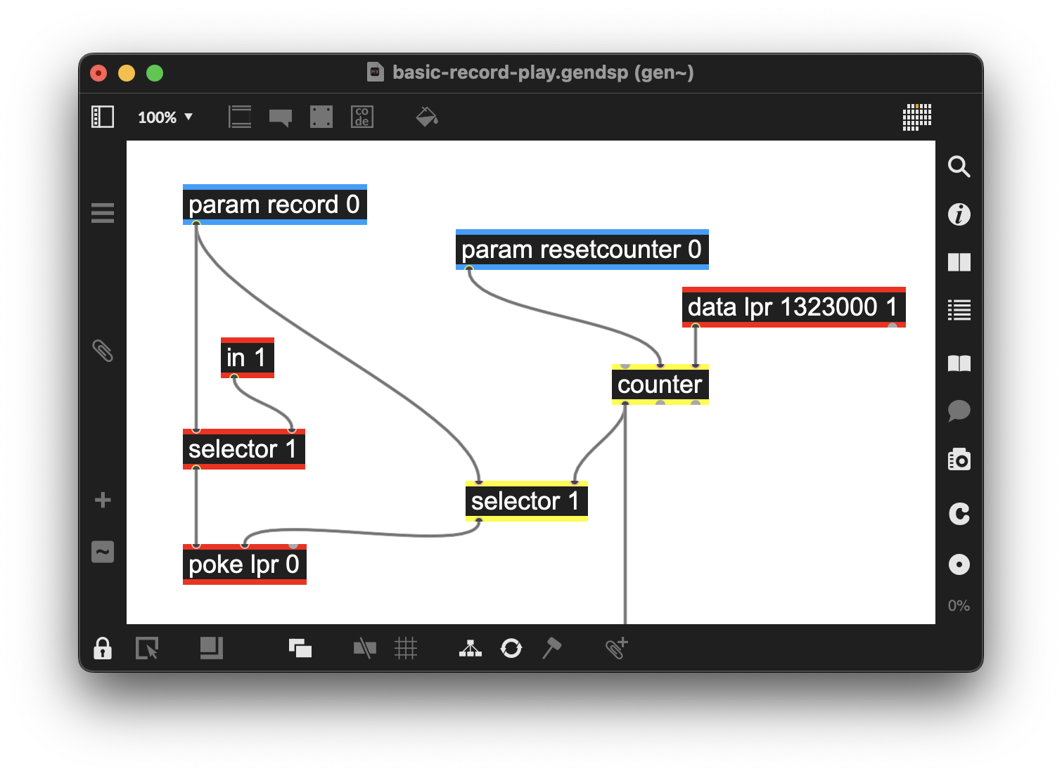
Figure 3-14
In our parent MSP looper patcher, we can control this using a single message box containing two messages separated by a comma. The order of the messages is important: the reset must be made before we start recording.
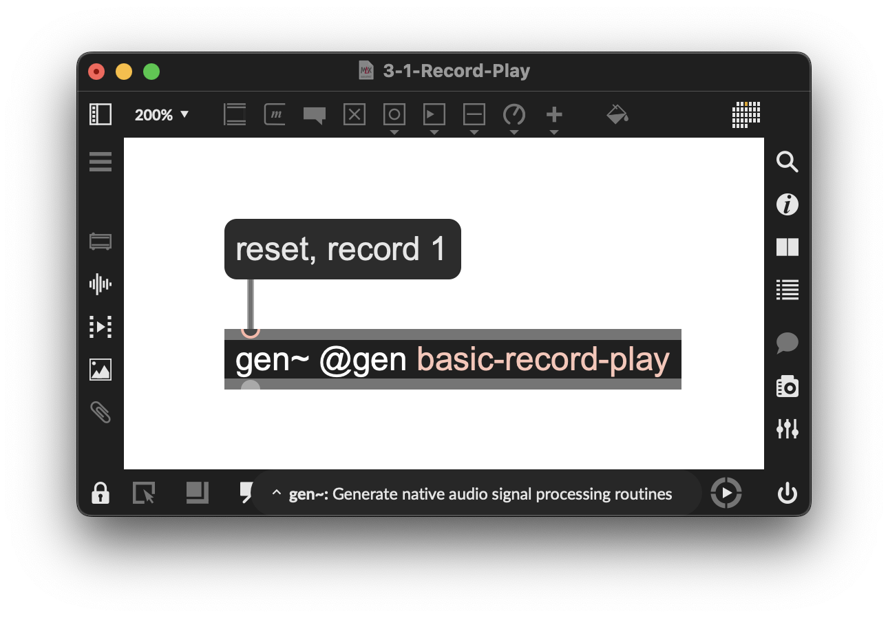
Figure 3-15
Once we have audio stored in the data operator, how do we read (play) it?
First, we need to set the end (length) of the loop to be played, i.e., when we stop recording. Since we restarted the counter to 0 when recording, once the end is set, we have a loop. To do this, we will use a second counter for playback set with the latch operator. The latch operator is similar to Max sample and hold objects—single-sample data (in this case, the current sample location in the buffer we are writing data to) flows through the operator until it receives a non-zero value in its left inlet, at which time the last value will be input until the next non-zero input. We’ll use the latch operator to set our second playback counter to a maximum value. When the counter reaches that number, it loops back to zero. We’ve added a param latcher 1 operator attached to the latch that tells it when to “latch” (set) the maximum length of the loop. Again, when the latch operator receives non-zero values, it simply passes the counter value through until it is instructed to store and hold that value as the end of the counter.
We also need to tell this counter operator to reset (1) or to run (0). However, the input from the param play operator comes from a toggle object in the parent patch. How can we send the opposite of the param play 0 operator’s input to the latch? We can do this using a !- 1 operator, which will “flip” that toggled parameter input such that an incoming 1 becomes a 0 and an incoming 0 becomes a 1.
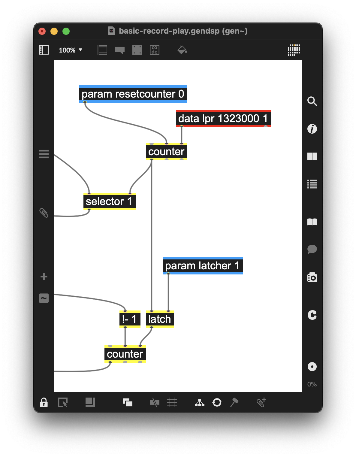
Figure 3-16
Finally, we need to inform the peek operator of the sample location from which it is retrieving data from the data operator. To do that, we add a selector operator to the output of the second counter operator. While playback is enabled, the selector operator sends the current sample count for the audio loop we’ve recorded to the peek lpr 1 operator and outputs the result.
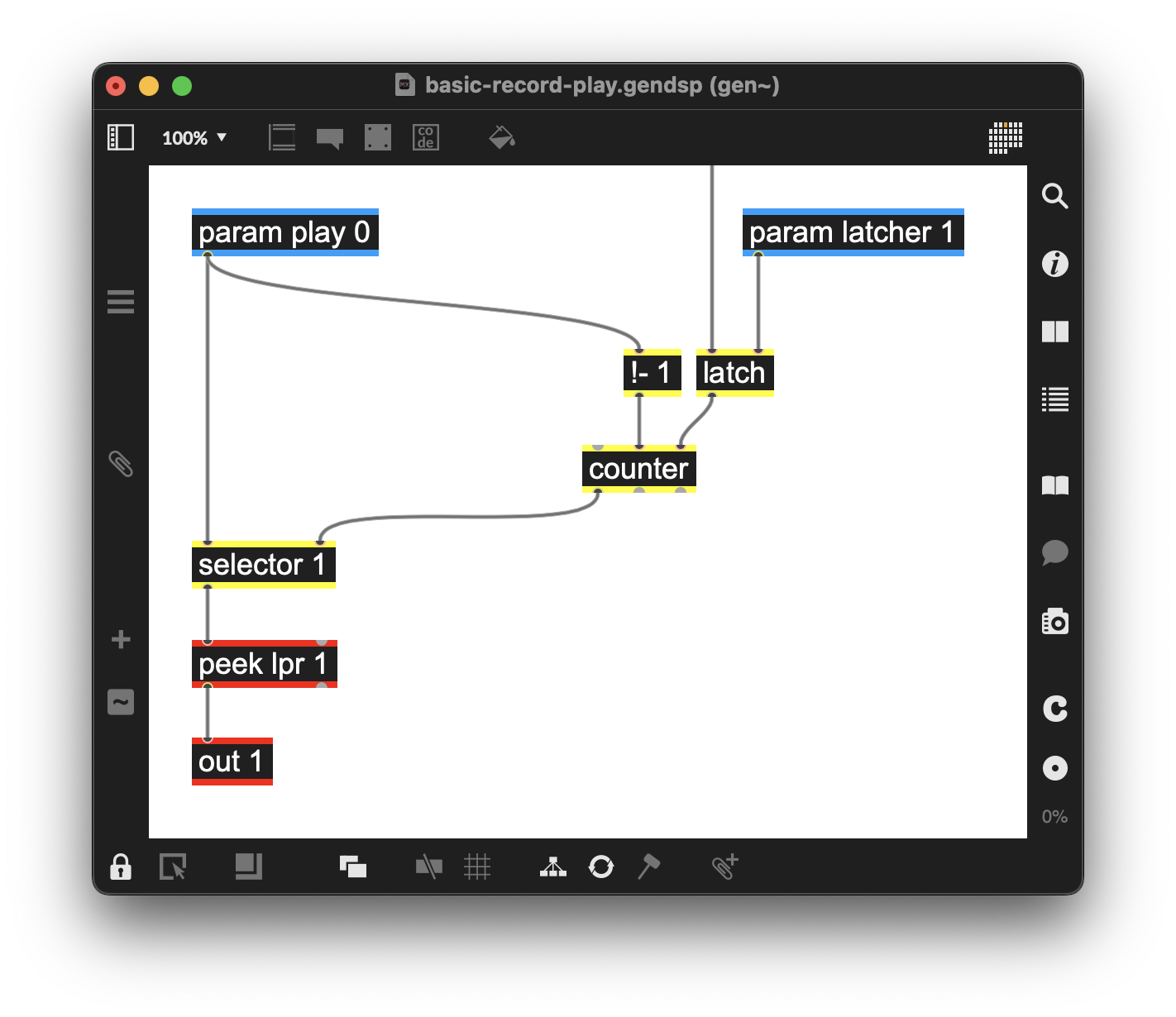
Figure 3-17
Here’s what the completed gen~ patcher now looks like:
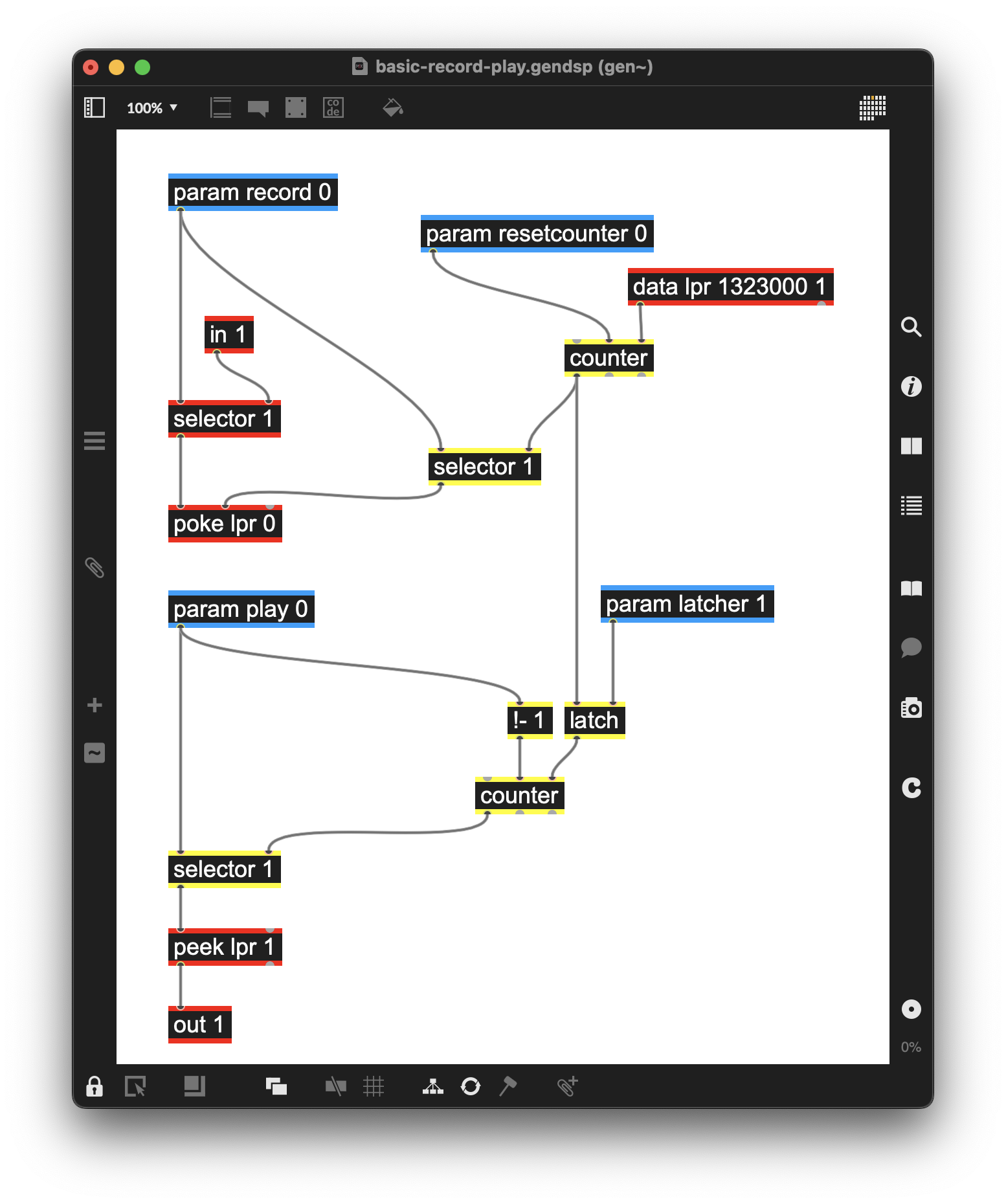
Figure 3-18
To see a large annotated gen~ patcher for this section, open the example patcher and double-click the gen~ to see its contents.
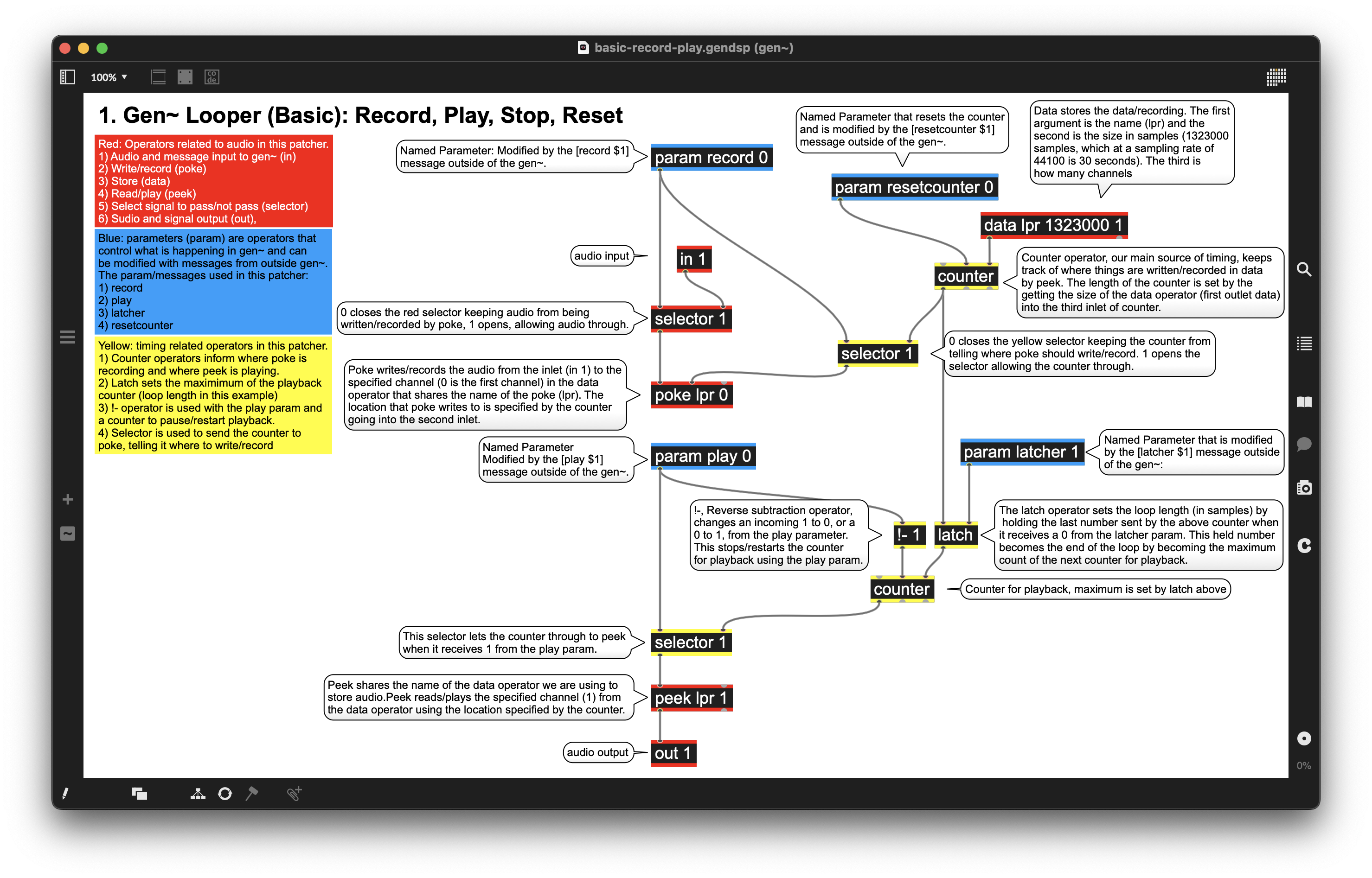
Figure 3-19
Wrapping it all up
Now that we’ve got a working Gen looper patch, it’s time to connect it to our parent patcher, add some control patching, and create a UI for the patcher.
You may have noticed that all the gen~ patchers in the Project folders distributed with this book are saved as .gendsp files. We do this for the same reason we save Max patches as abstractions—to give us bits of patching we can refer to by name and reuse. Gen patches saved as .gendsp files are just that. There’s also a pedagogical benefit for doing this from your point of view, too: if you make an accidental deletion or error while you’re patching, you can always reload the .gendsp abstraction to return to the original.
Sending messages from Max to gen~
There are a couple of situations where we’d like to control our gen~ abstraction (which appears in the Max patcher as a gen~ @gen basic-record-play object):
- To stop everything, we send the message reset, which sets all param operators to their default state.
- To record, we send two messages to the gen~ object: a reset message to reset everything, followed by the message record 1, which starts counting samples to record, and turns on the poke lpr 0 object to start writing samples.
- To play back our recorded loop. A record 0 message disables recording, the latcher 0 message sets the maximum sample count for our loop, the resetcounter 1 message starts counting at 0, and the play 1 message starts reading from the lpr buffer operator. To stop playback, we simply set the play param to “0.”
Here’s what the message box objects that send those messages to the gen~ @gen basic-record-play object look like. (Note that the messages are sent in a specific order in each box, and each message is separated from the previous one by adding a comma.)
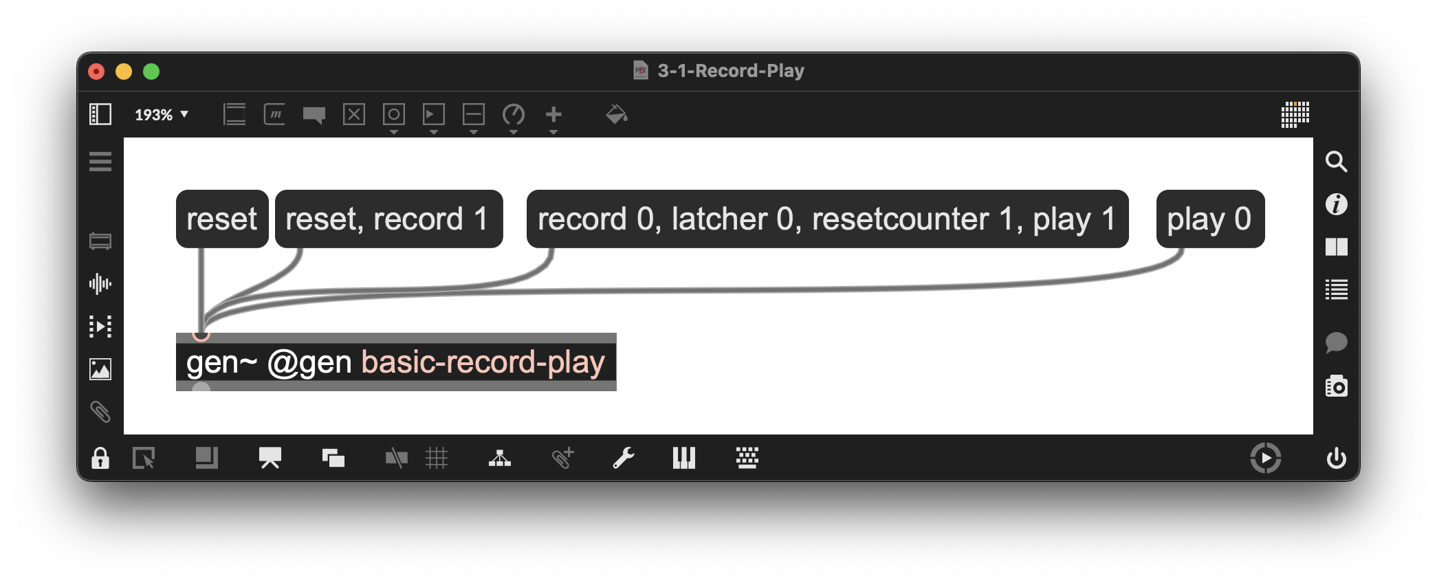
Figure 3-20
As you’ve probably noticed, we have four message box objects that contain all the messages necessary to record, play, stop playback, and reset our gen~ patcher. Grouping things in this way means that we can use a Max sel (selector) object to choose all four modes with a single number value, which determines which of the four sets of messages we send to the gen~ object. This will make creating a user interface for our patcher much simpler.
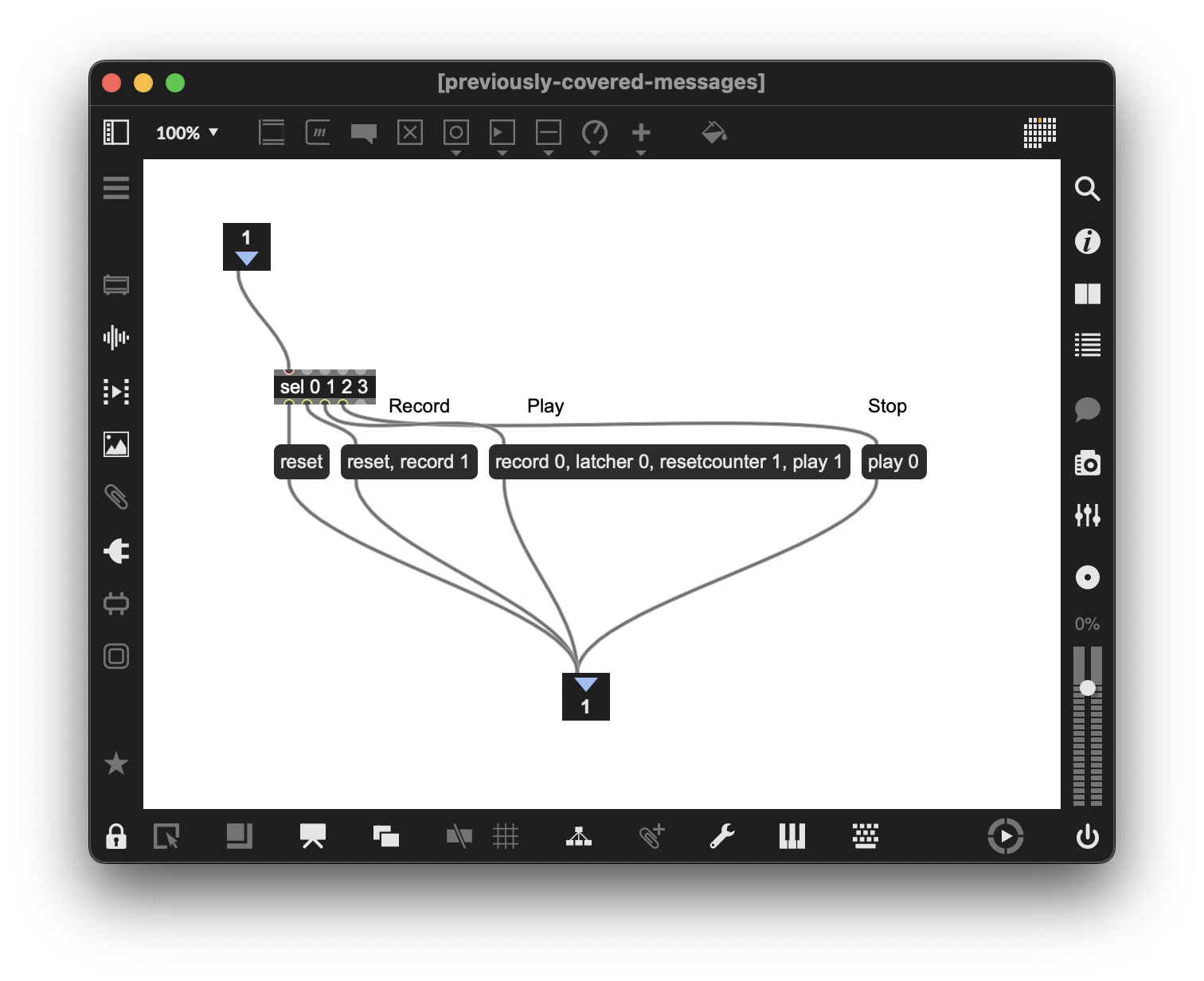
Figure 3-21
In our earlier patcher examples, we added mixing options and used the spacebar to turn the patcher on and off. For this patcher, we only need to select one of four messages (reset, record, play, stop). We can add a live.tab object to our patcher. It functions as a labeled multibutton object.
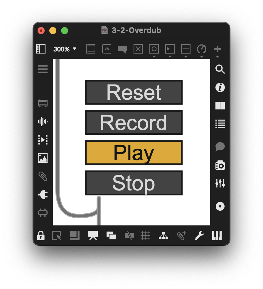
Figure 3-22
Create a new object and type “live.tab.” In the inspector for the object, in the “Range/Enum” section, select “edit” and type “Reset Record Play Stop.” Then, a bit below that, select Initial Enable and set it to 0 so that it selects the “Reset” option when the patcher is opened.
We will use the live.tab object with sel to send a bang to the desired message. Reset (0) goes to the reset message, Record (1) goes to the record message, etc.
Adding Overdubbing to a gen~ Looper
(Example Patcher: 3-2-Overdub)
For the next patcher, let’s add the ability to overdub audio input to what we’ve already recorded.
The Gen poke operator already has an overdubbing function built into it. If you mouse over the third inlet to our named poke operator, you will see a bubble that says, “overdub mix: amount of original signal to preserve.”
Based on the information about the overdub attribute, we will add a param mix 1. operator to our patch. A value of 1 for the argument sets the operator’s initial state, preserving all the original audio signal data. The parameter’s range is from 1.0 (100 percent of the original signal preserved) to 0 (no original signal preserved). This allows us to make creative choices in how our overdubbed audio is mixed.
When we use our patcher for overdubbing, we’ll want to overdub onto what we just played. That means our poke for writing needs to receive the counter we are using for playing: if you use the counter that has as its length the full data operator, it might not overdub where we want. We need to tell the poke operator what our count is to write the overdubbed signal to the correct location. To do this, we will modify our selector operator—going into our poke operator—to select either the data operator counter (full-length) when first recording (1), or the play counter for overdubbing (2). We do this by adding a + 1 to the output of the play param mix 1. operator. This change changes the functionality to do three things:
- Choosing between the two counters
- Also, starting the play counter
- Opening the selector 2 operator to send the counter value to the peek lpr 1 operator (play).
One last thing: we have added a “-1” between the selector and poke. This offsets the recording counter by one sample relative to the playback counter, preventing poke from writing to the same data location that peek is reading at that moment. Without this offset, unpredictable behavior can occur.
The math here is a little fudged, but it works—and in this case, stability and simplicity is more important than elegance. A one-sample delay—1/44,100 of a second at a 44.1 kHz sample rate (or proportionally less delay at higher rates)—is effectively inaudible, while providing the predictability we need.
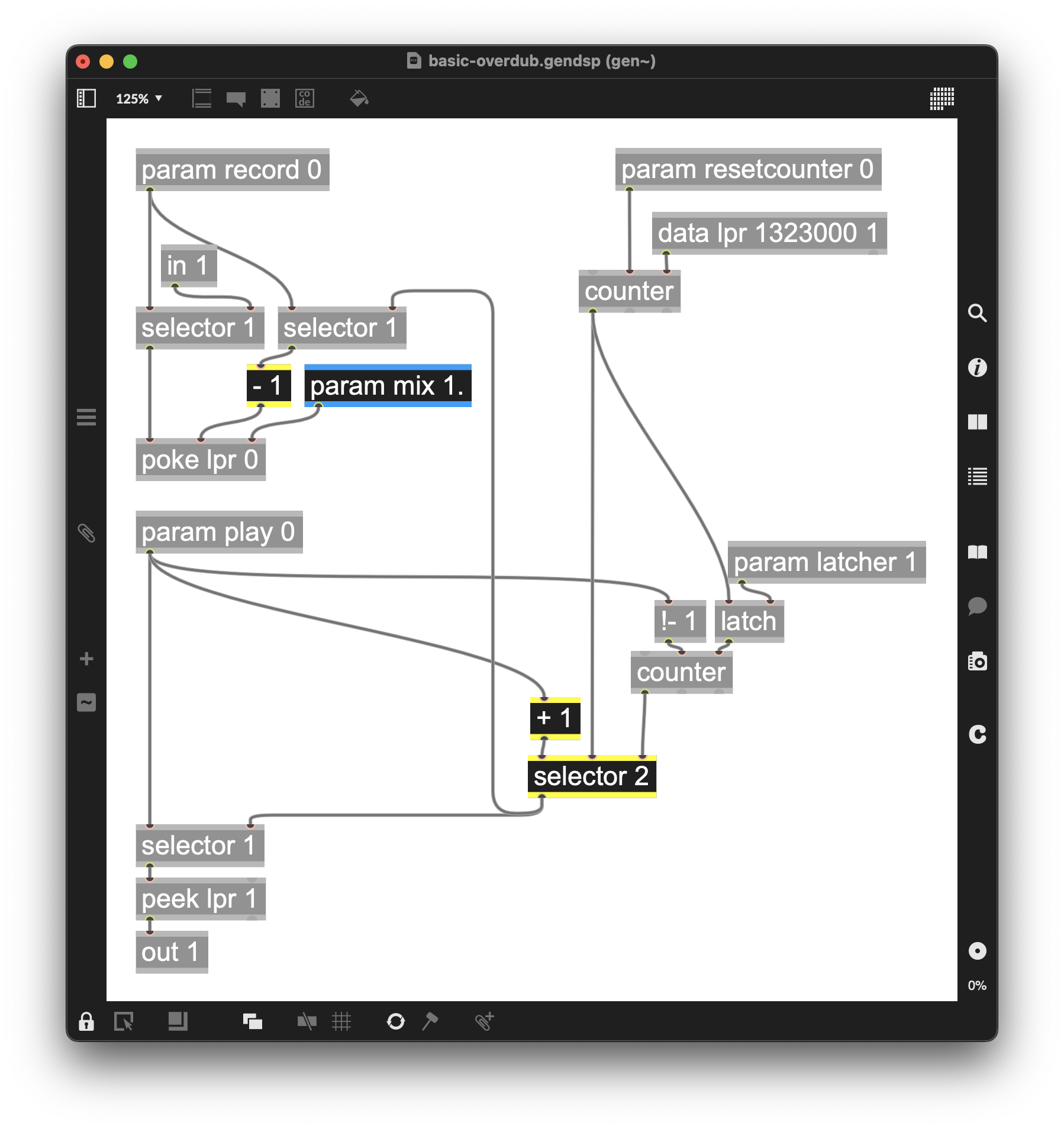
Figure 3-23
Performance UI
To simplify the patching for the set of control messages and our live tab object, we can move that part of our patch to a Max subpatcher (p previously-covered-messages in the example patch) created with the “Encapsulate” option in the “Edit” menu. As we move through each section of this chapter, we will use this to declutter the main window.
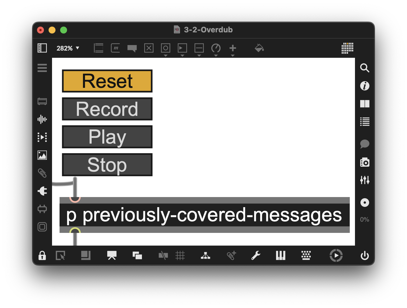
Figure 3-24
Here’s the inside of the sub-patcher:
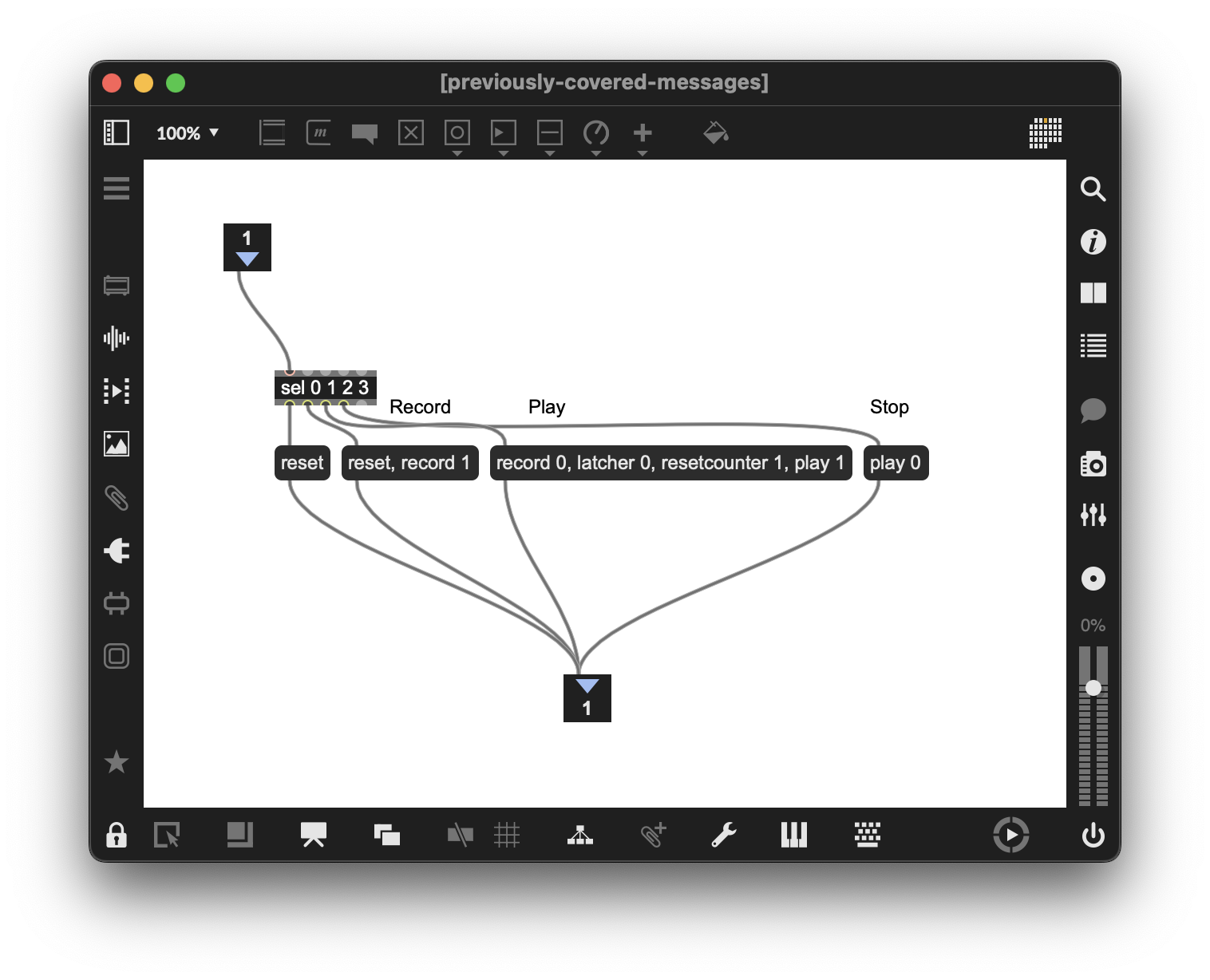
Figure 3-25
To enable overdubbing in the gen~ patch, we’ll add two new messages going into gen~: record and mix. Then use the combination of live.text object whose text will read Overdub Off/Overdub On which sends a record 0 or 1 message to the gen~ patcher. Along with this, a live.dial (as described in our first chapter) with messages that use a replaceable argument ($1) in a message box to set the amount of the original signal to preserve when overdubbing.
The record message for overdubbing is the same as we used earlier, but now we are using the play counter to know where to record. We are now recording while playing and using the overdub feature of the poke operator to preserve the original signal as we overdub.
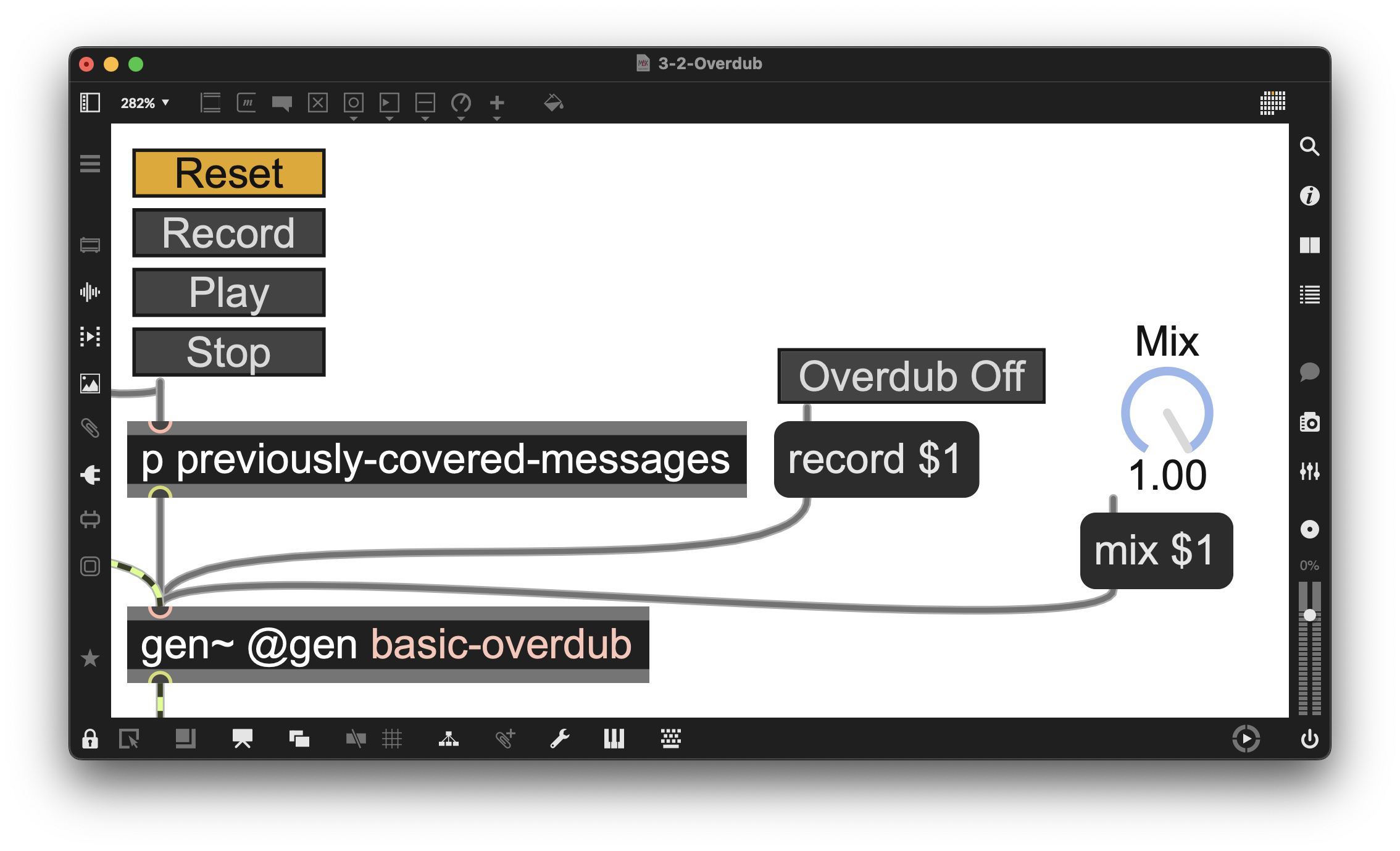
Figure 3-26
Removing Clicks in a gen~ Looper
(Example Patcher:3-3-Declicking)
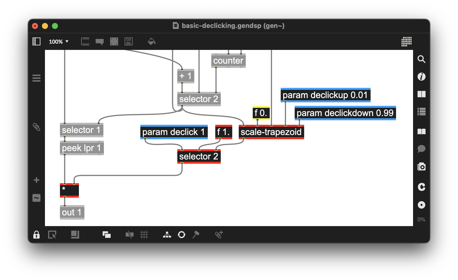
Figure 3-27
When capturing, manipulating, and playing back audio, we often encounter clicks in the output that need to be managed. (The clicks occur whenever we create discontinuities from one sample to another in the course of overdubbing or enabling recording.) While you may choose to embrace the clicks as an aesthetic decision, there are several methods you can use to remove clicks from your output.
We’ve already seen two examples earlier in this book:
- We used a gate~ with the @ramptime attribute when recording the audio into our patcher to prevent clicks in Chapter 1.
- We used ramping, interpolation, and introduced the trapezoid~ object to window our loop in Chapter 2.
This time, we will explore a way to use a gen~ patch similar to the trapezoid~ object, differing in that it is inside our gen~ patcher.
We have created a Gen abstraction (you can make abstractions inside of gen~ just as you do in Max) called scale-trapezoid. As with the trapezoid~ object, we specify the point at which the fade-in and fade-out functions are applied to the audio output (we use the param declickup 0.01 and param declickdown 0.99 operators to set the default values).
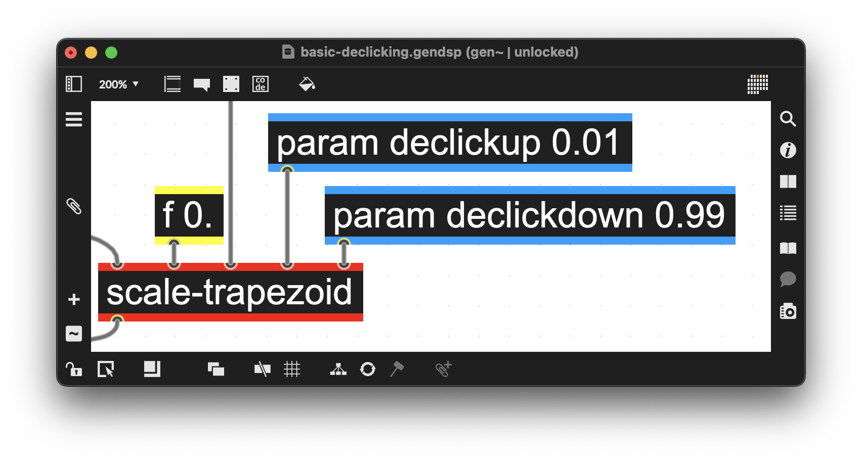
Figure 3-28
The release of Gen includes some patchers to create a trapezoidal function; the example can be found in Max->Help->Examples->gen.
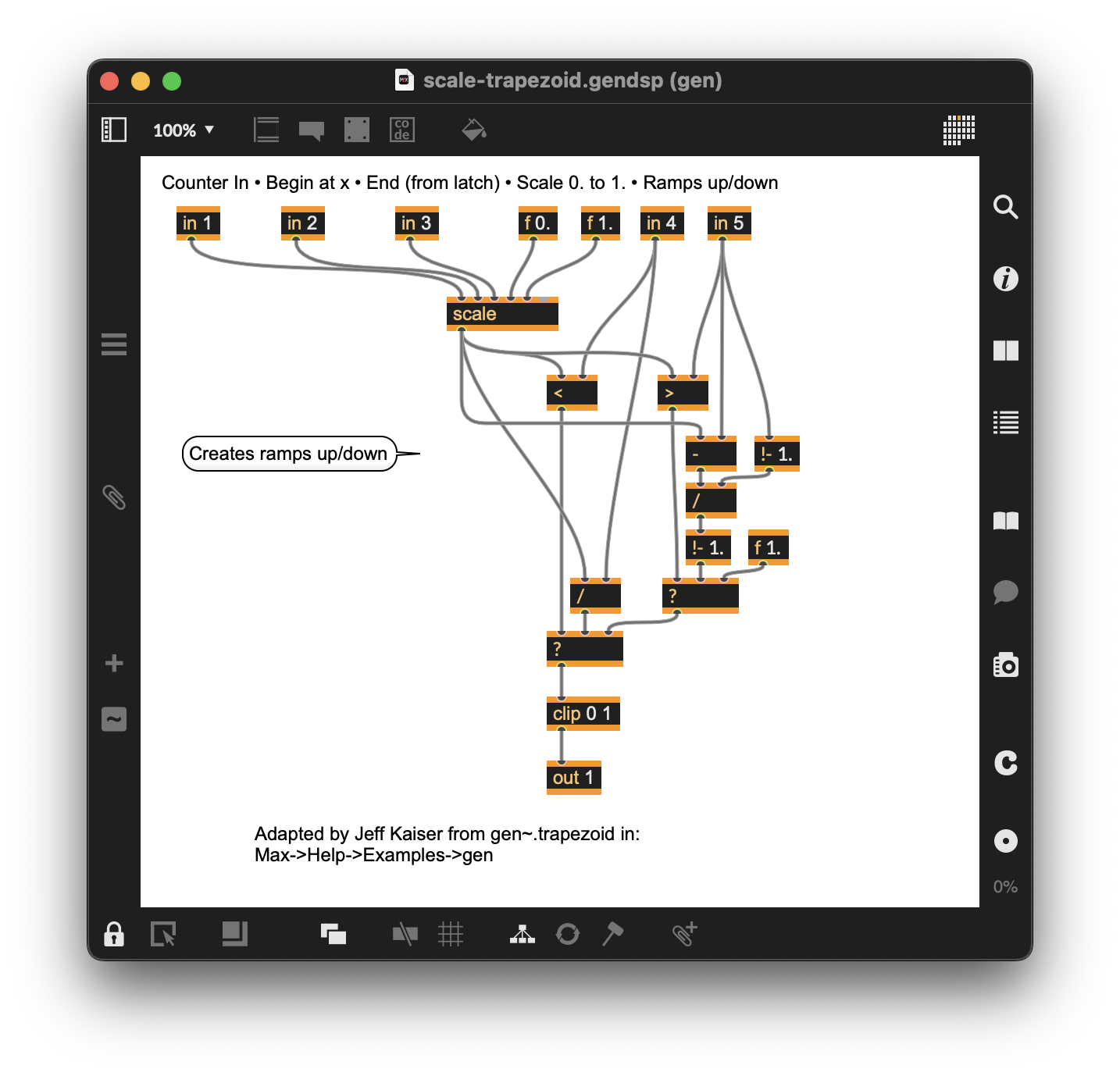
Figure 3-29
Double-click the scale-trapezoid abstraction to open it and examine its contents. Our modified version of the example creates an amplitude ramp at the beginning and end of the loop to help minimize clicking during playback.
It first gets the endpoint of the loop from the latch operator, uses the f 0. operator as the startpoint, and then scales those values from the incoming counter operator from 0. to 1. It then uses the value from the param declickup 0.01 operator to create a ramp up at the beginning from 0. to 1. and the value from the declickdown param to ramp down from 1. to 0. It sends these changing ramp values to the multiply inputs (*) operator to create the amplitude ramp during playback.
The selector following the abstraction uses the param declick operator’s value to select the constant float (f 1.) or select the changing ramp output of the abstraction scale-trapezoid. The float operator (f 1.) sets the multiply inputs (*) operator to 1. when declick is not selected.
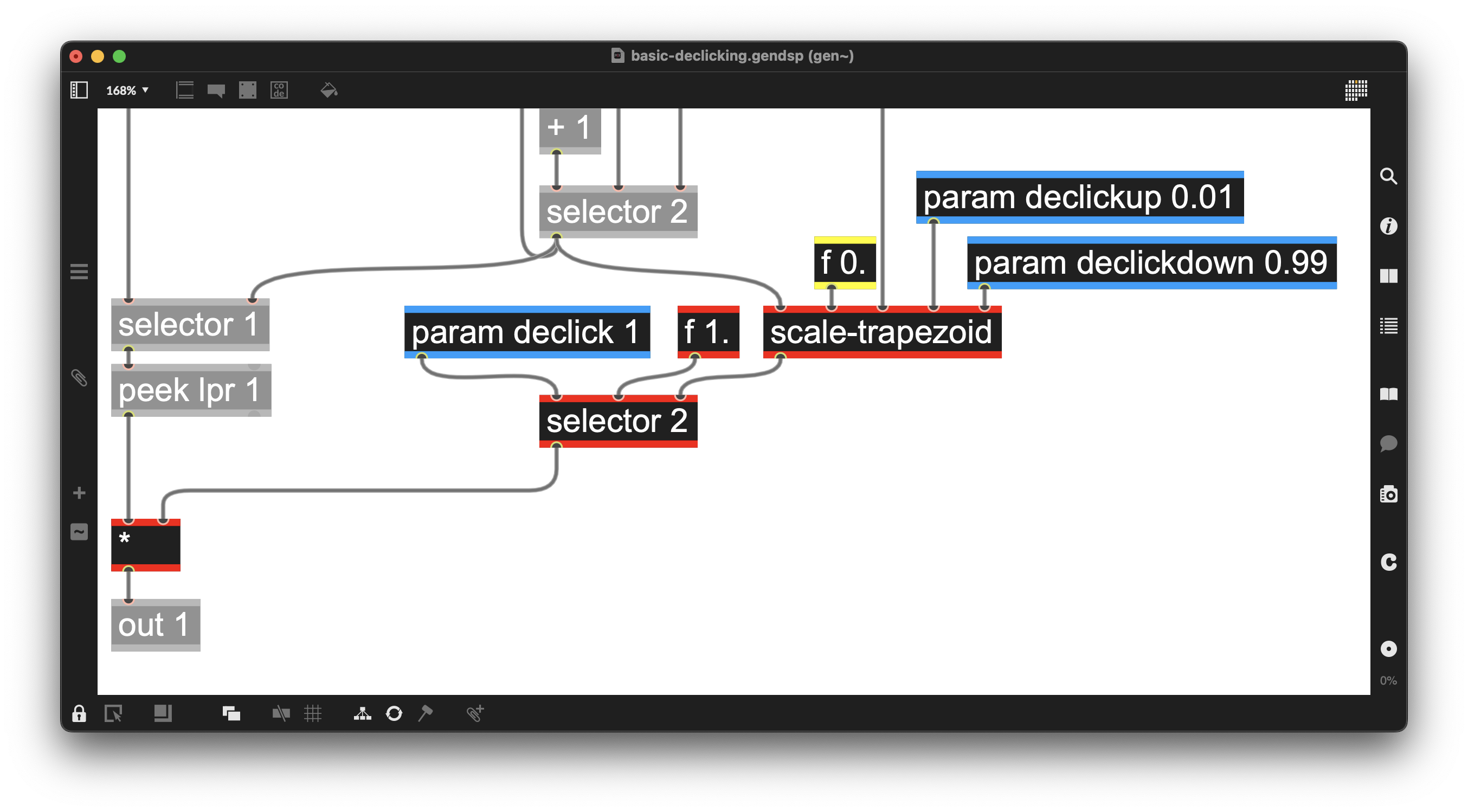
Figure 3-30
Performance UI
For the performance UI, we have added a live.text object used as a toggle with messages that use a replaceable argument ($1) in a message box to turn declicking on/off, and two live.dials to set the ramp-up and ramp-down times using a similar message box technique.
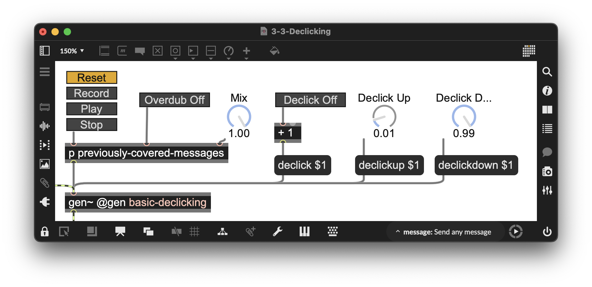
Figure 3-31
Shortening Loop Length in gen~
(Example Patcher: 3-4-Shortening)
We will next explore shortening the loop length and then using selector operators to switch between playing the full loop, the shortened loop, and the remainder from the shortened loop.
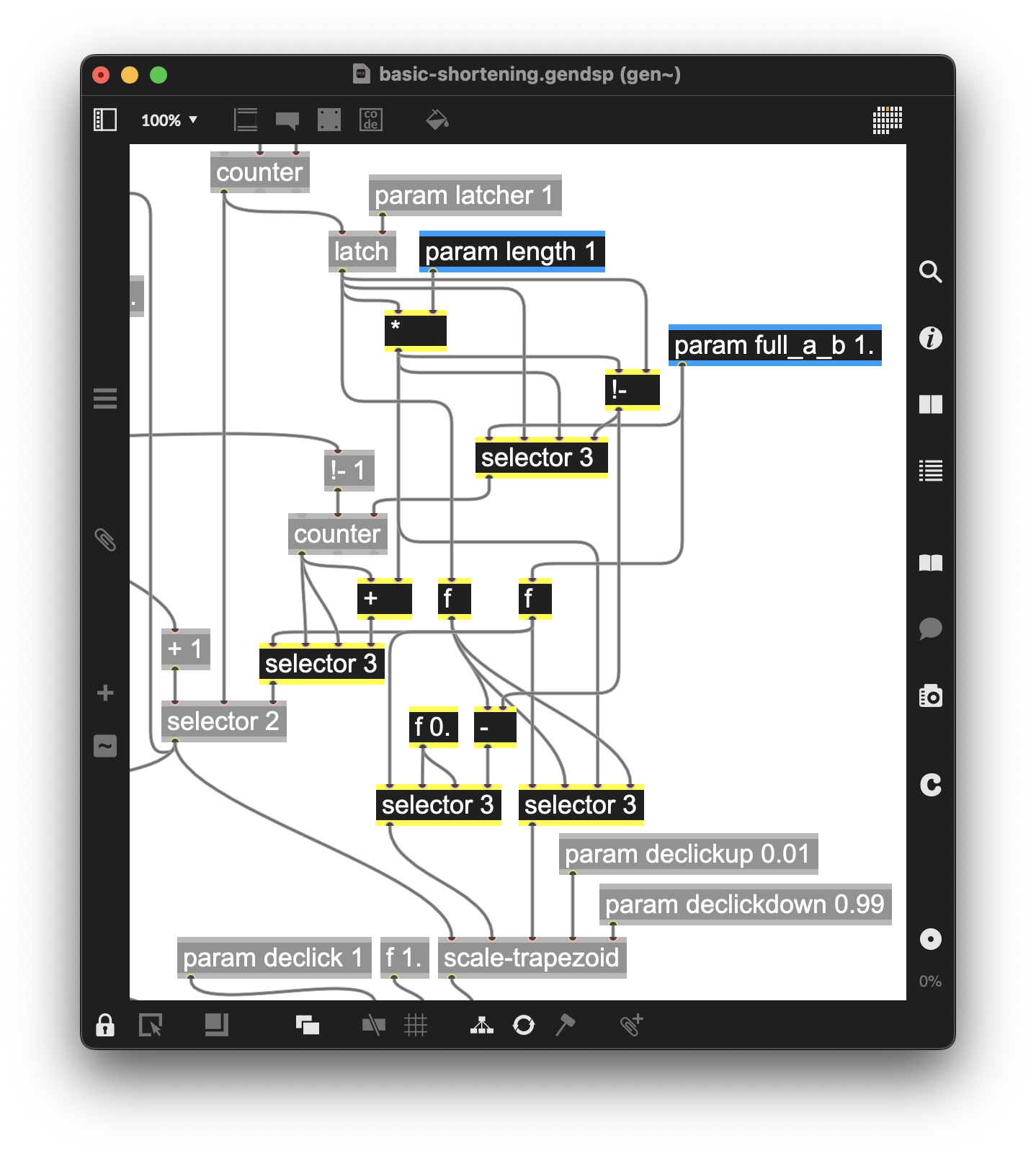
Figure 3-32
Shortening is accomplished simply by multiplying the length of the loop (given by our latch operator) by a number less than 1. For this example, we use the multiply inputs operator (*) with a param length 1 operator (for our patcher, we will refer to this shortened loop as A). We then also subtract the shortened length from the full length, and that value becomes our B. We can then get three loop lengths from the latch operator’s output going into our first selector:
- The full loop length in the selector 3 operator’s first inlet
- The shortened loop length (A) in the selector 3 operator’s second inlet
- The remainder (B) in the selector 3 operator’s third inlet.
This selector operator’s output sends the result to both latch the playback counter and to the input of the declicking abstraction. The other selector operator chooses which one to use for playback: inlet one is “full,” inlet two is “A,” and for the third inlet, we add the shortened bit (A) to give us the starting point for the remainder “B.”
Modifying Declicking
We are now managing playback from three different possible locations:
- Counting samples from 0 to the value stored by the latch operator (full recorded loop).
- Counting from 0. to a shortened latch value (A)
- Counting from the end of the shortened latch value to the full latch value (B).
Since each of these possible playback locations involves different sample lengths, we will need to adjust the declicking section of our patcher to work with those ranges. We can use the param full_a_b 1. operator we already have to do this—its output is routed to two selector operators. One selector operator calculates/sets values at the start of the loop, and one selector operator calculates/sets values for the end of the loop, setting our scale-trapezoid abstraction as needed. (The two f operators act as distribution points for latch and param full_a_b to not have so many patch cords going through the middle of the patcher.)
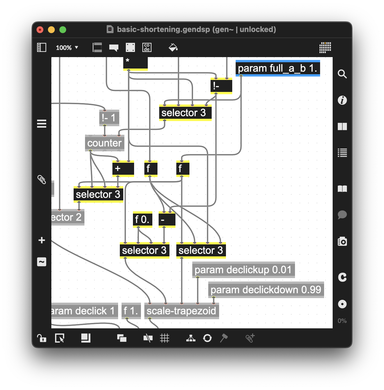
Figure 3-33
Performance UI
For the UI, we have added a live.text/+ 1 object pair used as a switch, a message using a replaceable argument ($1) in a message box to select shortened loop lengths, and a live.dial operator using a replaceable argument ($1) in a message box to set the new loop length.
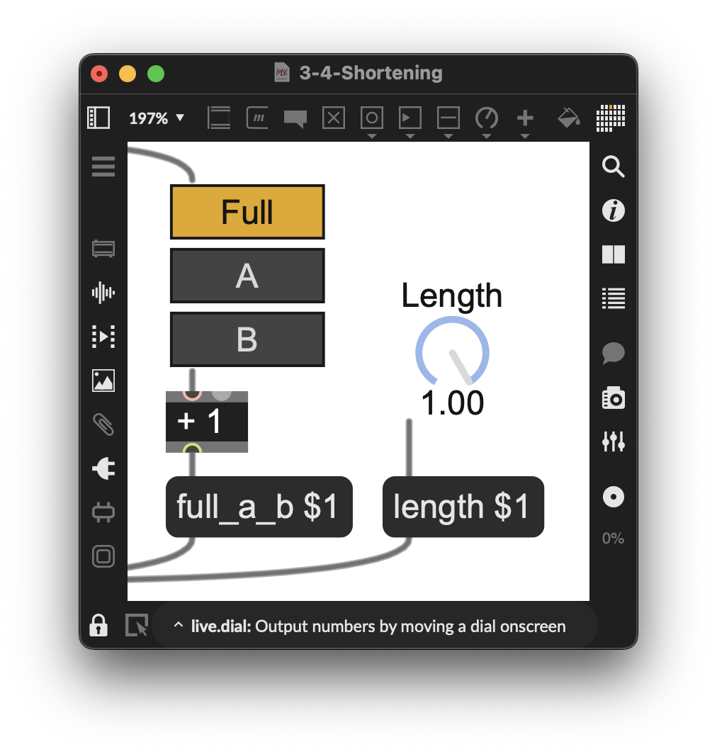
Figure 3-34
Auto-Insert and Rhythmic Overdubbing
(Example Patcher: 3-5-Auto-Insert)
Up until now, we’ve been adding features to this patch by modifying the contents of the gen~ object. For this feature, we will provide metrical/rhythmic control of the overdub on/off for creative overdubbing—inserting/replacing audio depending on the mix setting—solely by patching in the Max environment.
If a Max user interface object, such as a toggle or live.text object receives a bang message, it reverses its current state from 0 to 1 or 1 to 0, and outputs the new value. Since a metro external object outputs bangs at a regular rate, we can use that output in combination with a toggle (or a live.text object, in this example) to rhythmically turn something on and off. We’ll combine this with the overdub functionality we have already added to our gen~ patcher to turn overdubbing on and off for creative, rapid-fire overdubbing or experimental rhythmic effect. (We’re using the metro object in this example, but you could use random functions to create delightfully chaotic patterns and more.)
We start by adding a metro object connected to our overdub on/off that outputs bang messages at a default rate of 250 milliseconds. Adding a connected routepass 0 object ensures that when we turn Auto-Insert off, it also turns off the Overdub On/Off toggle.
Next, we add a live.dial so we can vary the rate at which the metro object sends out bang messages (tempo).
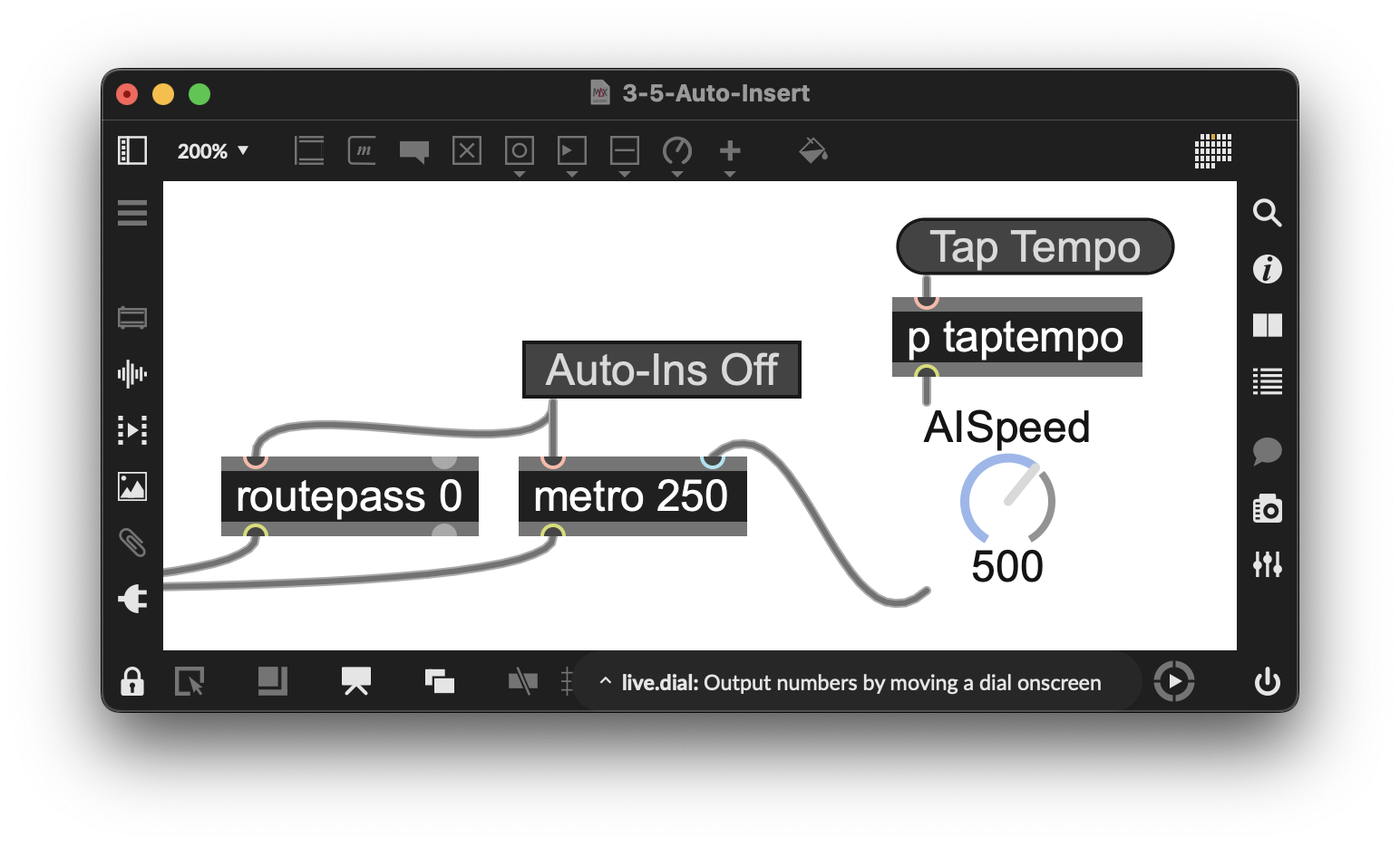
Figure 3-35
You’ll also notice that we’ve added a new Max abstraction (p taptempo) and a button labeled Tap Tempo. This will allow us to set a rate for auto-insertion by tapping a button. Here’s what the abstraction looks like (double-click the abstraction to see its contents):
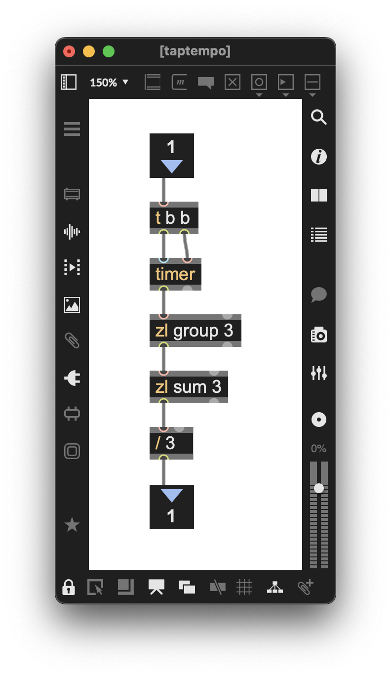
Figure 3-36
This simple abstraction uses a timer to measure the time between taps. It then groups and sums every three taps and divides by 3 to create an average time, which is then passed on to our live.dial named AISpeed.
We have also added a live.tab that allows you to quickly select a predetermined amount of the original signal to preserve when overdubbing.
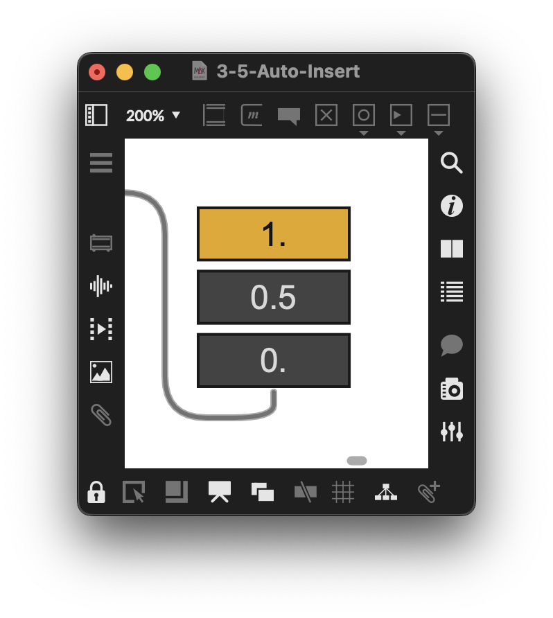
Figure 3-37
Randomizing Playback in a gen~ Looper
(Example Patcher: 3-6-Randomize)
For slicing and randomizing playback, we will combine objects both inside of gen~ and outside in the Max patcher. There are many ways to accomplish the randomization of playback. For this example, we will be doing three things
- Dividing the loop into multiple segments (slices) inside the gen~ object.
- Using a metro object to trigger and generate a random number in Max, with a message that will play the particular segment (division) corresponding to that random number
- Adding a live.text toggle that lets us select either “Regular Mode” (uses the counters for playback that we previously added) or “Slice Mode” (that uses what we will call the counter operator we’ll add that is used for segment divisions.
Dividing the loop
Inside our Gen patcher, we add a param segments 4 operator and / (divide) operator combination to set the number of segments (slices) we want. This divides our total loop length into the desired number of segments, giving us multiple new segment lengths to be played using the segment playback counter.
We instruct the count operator to play a specific segment by generating a random number within the range of the number of segment divisions in the parent Max patcher set, using the param random 1 operator in our gen~. The random parameter value, the * (multiply) operator, and the + (addition) operator work together to set the point at which the patcher starts and ends playback. We use the selector 3 operator to select the full loop, section A, or section B, for slicing, which increases our randomization options.
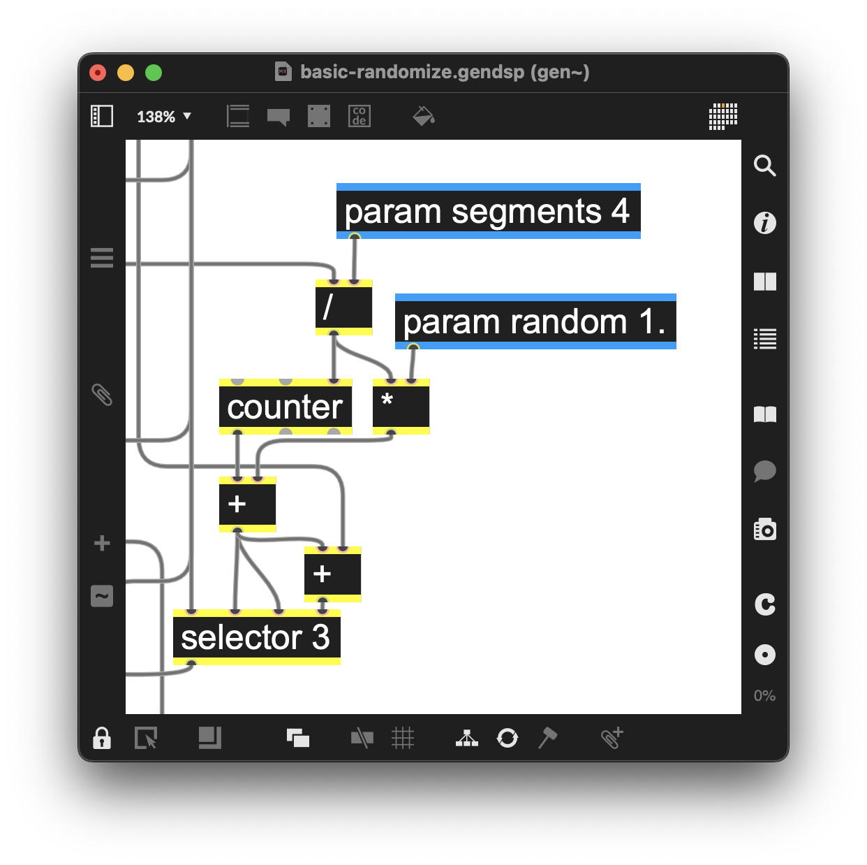
Figure 3-38
Finally, we use the new param mode 1. and selector 2 operator pair to choose either Regular Mode, which plays back with our previously made playback counters in the first inlet, or the new segment counter (Slice Mode) in the second inlet.
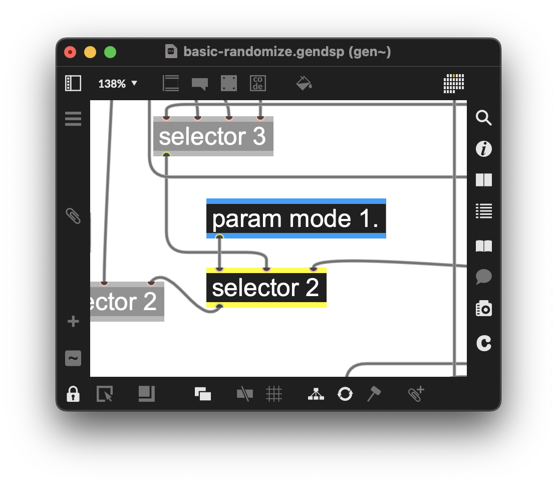
Figure 3-39
Performance UI
We’ll need to add a user interface that lets us control loop slicing and random playback. In the figure below, you can see we added a live.text object to select Regular or Slice Mode, a live dial object to select the number of segments/slices we want, and a metro/random object pair of objects to choose which slice to play. (Notice that we’re taking the output of the live.dial that sets the number of segments and using that value to set the upper bounds for our random number generation. Finally, we have repurposed the Tap Tempo abstraction we created earlier to allow us to tap in the tempo for the metro slice.
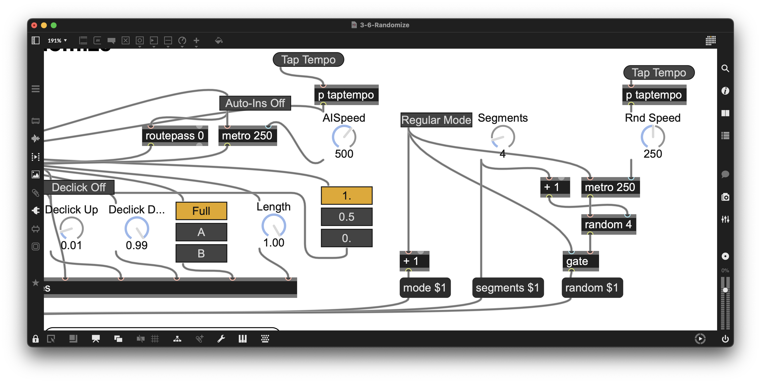
Figure 3-40
Changing Speed and Direction in a gen~ Looper
(Example Patcher: 3-7-Speed-Direction)
Changing speed and direction for playback with this version of a gen~ looper is easy, but it comes with a caveat: overdubbing with any speed and direction other than 1 in a forward direction can create unexpected artifacts, which may or may not fit with your aesthetic. We will explore varispeed overdubbing in our next chapter.
To change the speed of our loop playback, we need only change the value by which the counter counts. A value greater than 1 will increase the speed, and a value between 0 and 1 will slow it down (0 stops the counter, of course). We send this number to the counter operator by means of the param speed 1 operator.
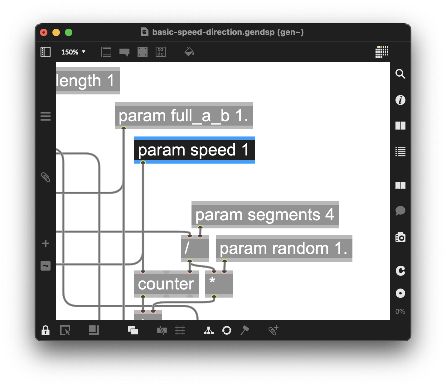
Figure 3-41
To change the direction of playback, we simply need to have our counter count backward. To do this, we once again add !-, the reverse subtraction operator that subtracts the first input from the second input. The param direction 1 operator, in combination with an added selector 2 operator, lets us choose inlet 1 (the regular and slice mode counters) or inlet 2 (that has those same counters counting backwards) with the !- set by the latch operator.
The param direction also serves double duty here. Because we still want the poke write position to remain one sample behind the peek read position, we previously applied a “-1” offset. When playback is reversed, however, that offset must become “+1” instead.
We accomplish this by using param direction to control a selector that chooses “-1” when playing forward and “+1” when playing backward, ensuring that the one-sample offset is preserved regardless of direction.
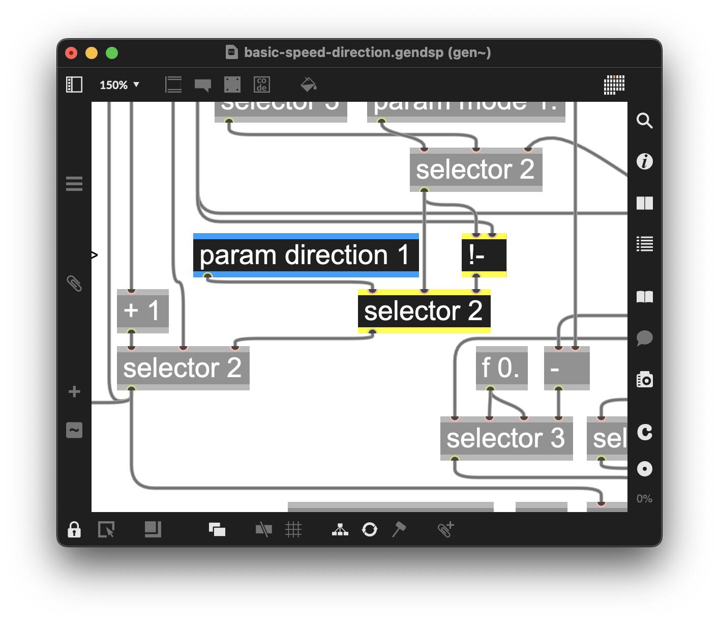
Figure 3-42
Performance UI
To control the speed and direction, we have added outside of the gen~ a live.dial object for speed control and a live.text/message box object pair to select whether the counters in our patch count forward or backward.
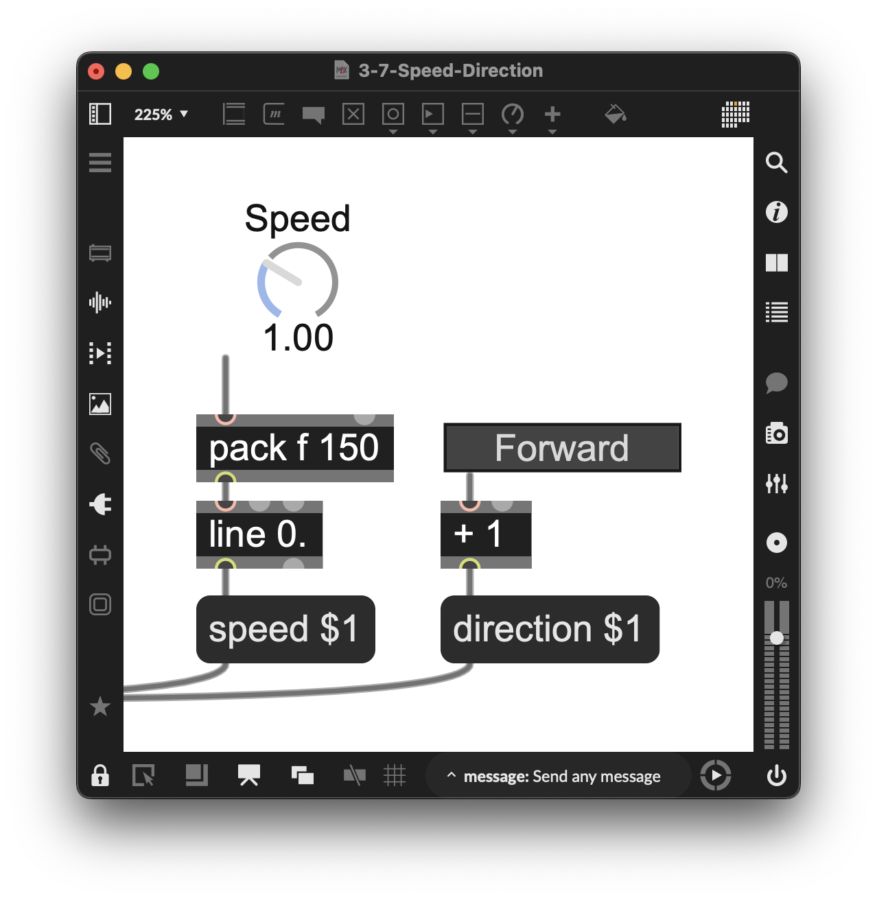
Figure 3-43
Performance UI
(Example Patcher: 3-8-Performance-UI)
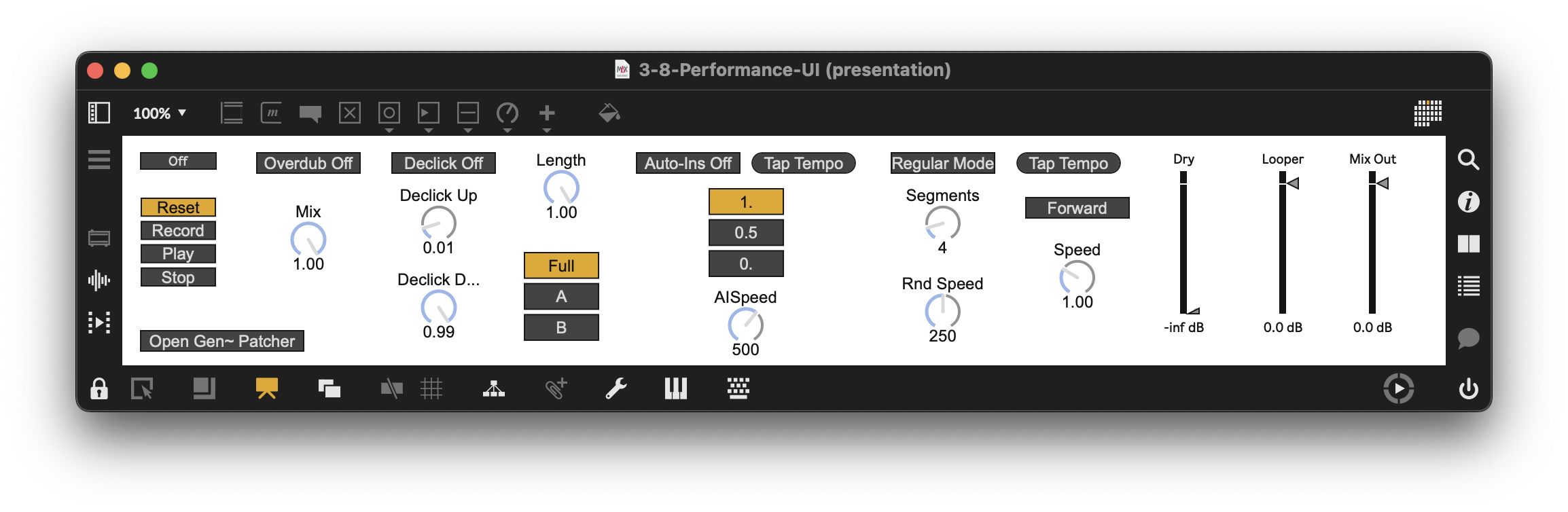
For our final patcher, we need to put it all together in a way that makes sense for performance. As we did in previous patchers, we’ll organize our user interface elements using Max’s Presentation view, adding only those UI objects to Presentation View (once added, we can identify them by their salmon-colored outline.
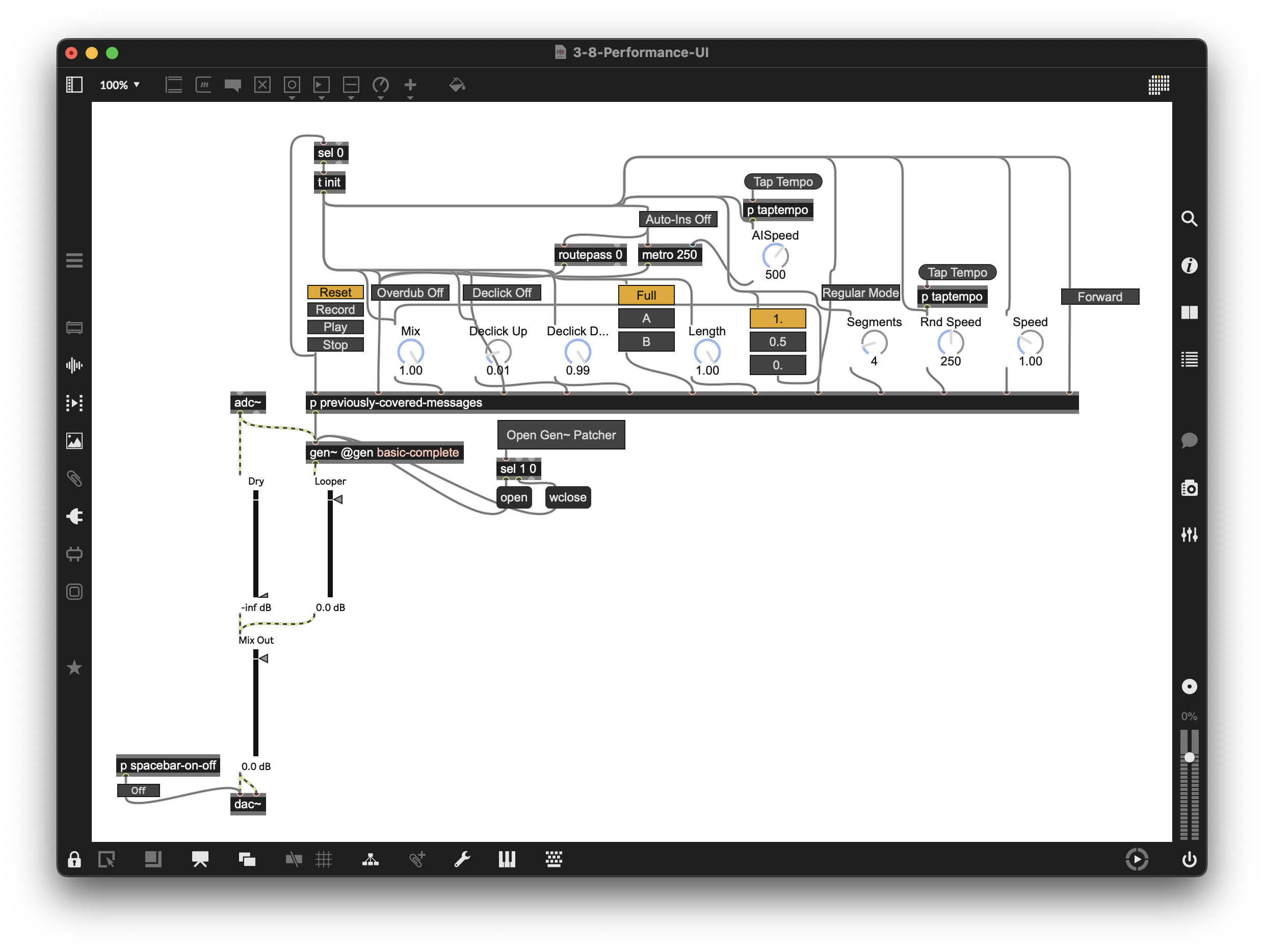
Figure 3-44
Toggling Presentation view lets us reorder the placements of objects added to the Presentation View in a way that makes performance easier and clearer.