Chapter 7 — Basic Overdubbing Looper (rnbo~)
In this chapter, we recreate the basic overdubbing looper from Chapter 3 in the rnbo~ programming environment, adapting familiar recording, playback, and counter-based techniques to support overdubbing and performance-oriented workflows. As we’ve seen when creating our sequence of loopers and transitioning from the MSP to the gen~ environment, we’ll look at four interrelated parts of the patch that you’ll recognize. Creating our RNBO patch will require revisiting those areas as we implement the new patch. We’ll walk you through each of the areas to provide an overview of how our patcher needs to be modified. The overview is essential because, as before, recording/playing/overdubbing is never a single message, but multiple messages as you turn one section on and another off while starting or directing a counter to a new section.
The Basics: Record, Play, Stop, Reset
(Example Patcher: 7-1-Record-Play)
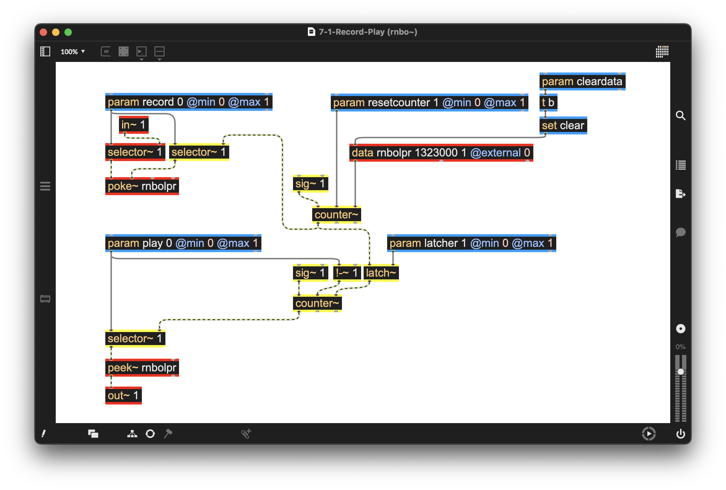
Figure 7-01
The core of this patcher is our data object, which strongly resembles the gen~ operator of the same name (its relationship is made more evident by the fact that the help files for both the buffer~ and the data operators are combined. We’ll use the data object as we used the data operator in our gen~ patching—as a purely internal (in this case, to the rnbo~ patcher) place to store the recorded audio through adding the attribute @external 0. Since we only use it internally, the internal-only use is part of the exported code; should we export it to a target.
The arguments for our data operator include a name (rnbolpr), memory size in samples (1323000), and the number of channels (1). As in previous examples, we have added the patching used to clear the memory on the incoming message “reset” (param cleardata) using a t and set object with the message “clear.”
The number of samples allocated to memory in data also sets the default length of the counter~ operator, via the connection between the two. The middle inlet of the counter~ is used to tell it to reset the count to 0, and the first inlet has a sig~ that instructs the counter~ object to run at normal speed (1).
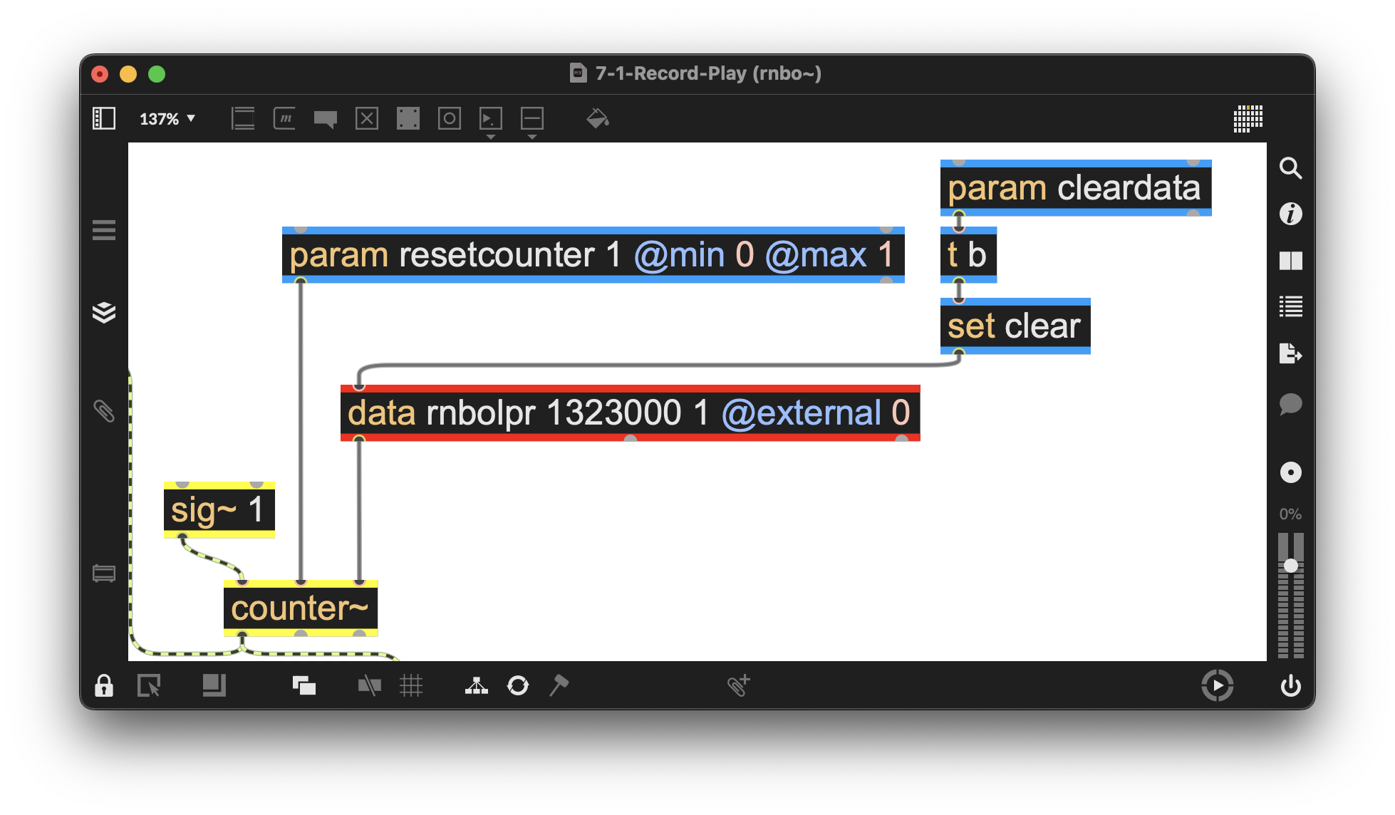
Figure 7-02
We use a poke~ operator to write to our data object in the recording section of our patcher. Our poke~ object has a single argument - a name associates it with its similarly named data operator. We have set up a param object named “record” with two functions: to open and close a selector~ that lets audio in to be recorded, and also opens a selector~ that lets in the counter~ which tells poke~ the location in our data object to write.
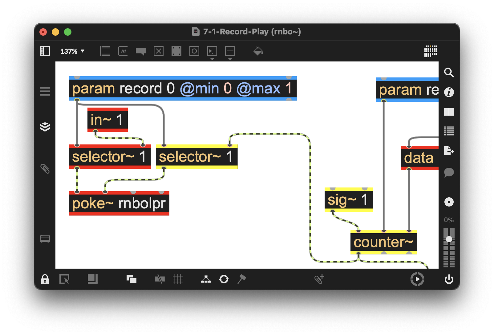
Figure 7-03
The playback portion of our patcher uses a peek~ operator for playback (reading) from the data object. As with the poke~ operator, our peek~ object has a single argument—a name that associates it with the data operator of the same name. Our param named “play” opens a selector~ that sends a counter~ to peek~ telling it what location to read. This counter~ is a second counter~ that uses a latch~ (controlled by the param latcher object), grabs the latching value from the counter~ (to which it is connected) to set the end of the second counter~ when we enable playback and turn off recording. The second latched counter~ provides how audio stored in the data object loops as it counts to the end of the latched value and starts again from 0. Every time you press play, it also resets that counter~ (using the middle inlet) to begin reading from 0. The sig~ operator’s argument of 1 ensures that the counter~ object runs at normal speed.
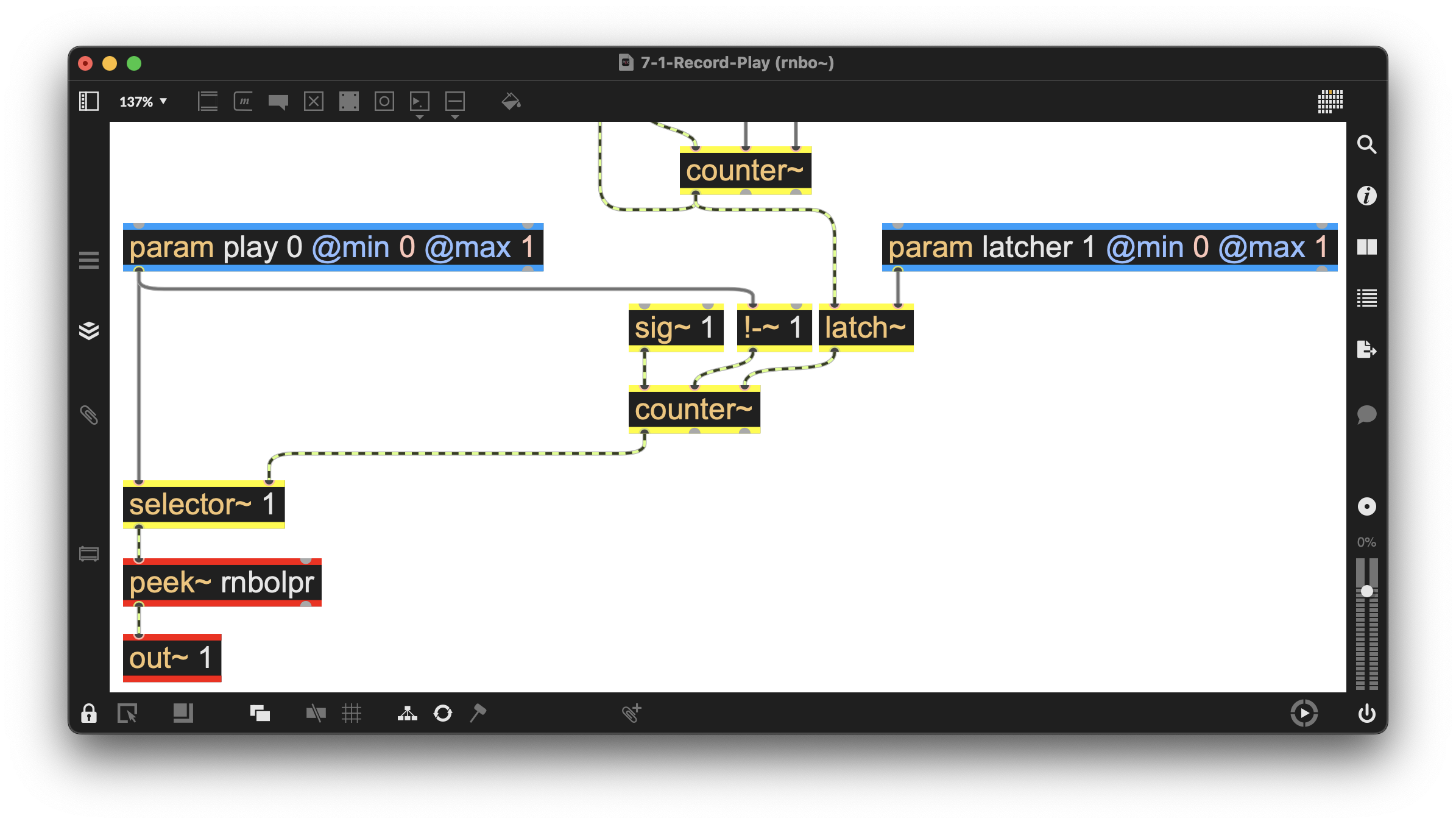
Figure 7-04
With this overview in mind, we see that many of our patcher’s basic functions (reset, record, play, stop) require a sequence of multiple messages.
The parent patcher shows us that sequence of multiple messages, each contained in a message box for the record, play, and stop functions:
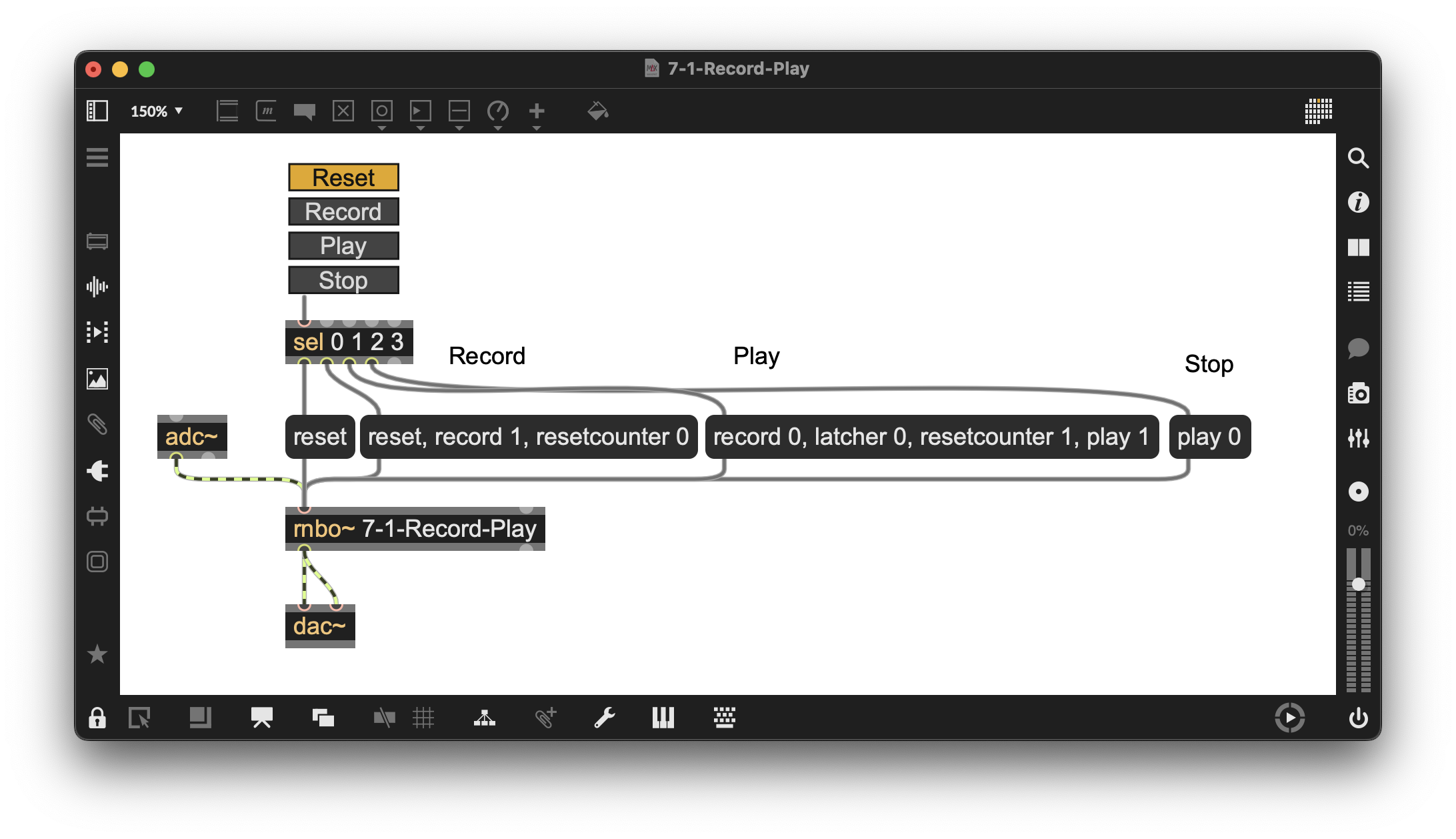
Figure 7-05
- For resetting, we send a generic reset message that sets the entire contents of our rnbo~ patcher to their default state.
- To record, we send the messages “reset,” then “record 1” to turn on recording, and “resetcounter 0” to have it start counting from 0.
- For playback, we turn off recording, latch the loop's endpoint, reset the counter, and enable playback.
- To stop, we simply close the selector~ so that no counter is sent to peek~.
Overdubbing
(Example Patcher: 7-2-Overdub)
To add overdubbing to our patcher, we’ll need to allow recording to work with the new latched counter~ that sets our loop. We’ll need to add a selector~ operator with two inputs to do this.
The first input is our main counter~, whose duration is specified by the connection to the data operator. This length sets the maximum possible duration for our initial recording.
The second input is our latched counter, which we’ll use for our loop playback. Param play controls, which counter~ is used via the selector. When overdubbing, we will also select the loop playback counter~ to instruct the poke~ operator on the location to record the overdub.
We will also add an @overdub accum attribute to our poke~ operator. The attribute sets the poke~ operator to add the new recording to the previously recorded content. We’ve also added param mix 1. @min 0 @max 1. object to set how much of the previous audio to preserve when overdubbing: 1. meaning that 100 percent of the previous audio recorded is preserved.
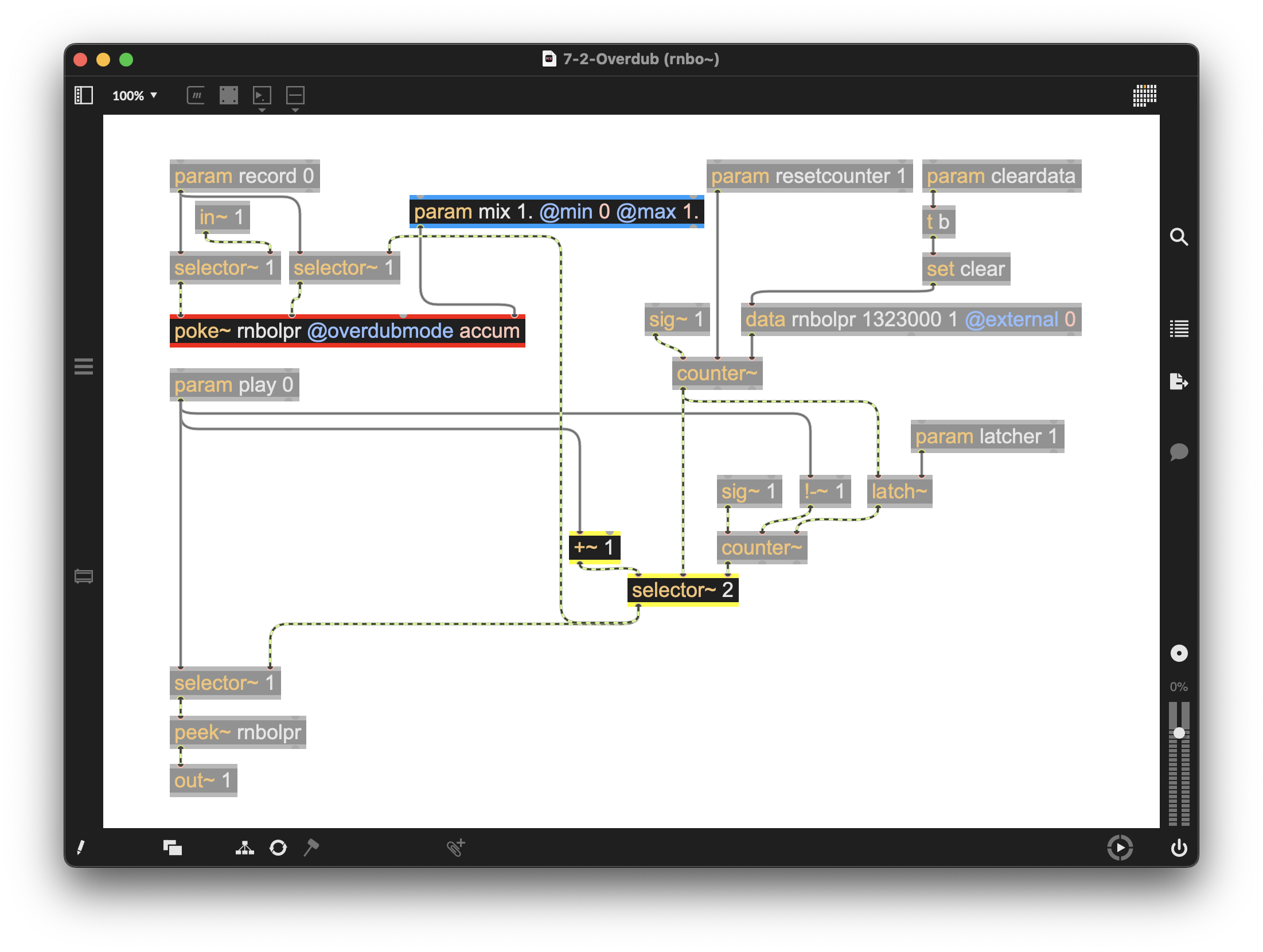
Figure 7-06
In our parent overdubbing patcher, we have added a “record” message and a “mix” message. As in earlier patchers, when reset is selected, it triggers an “init” message to our Live UI objects.
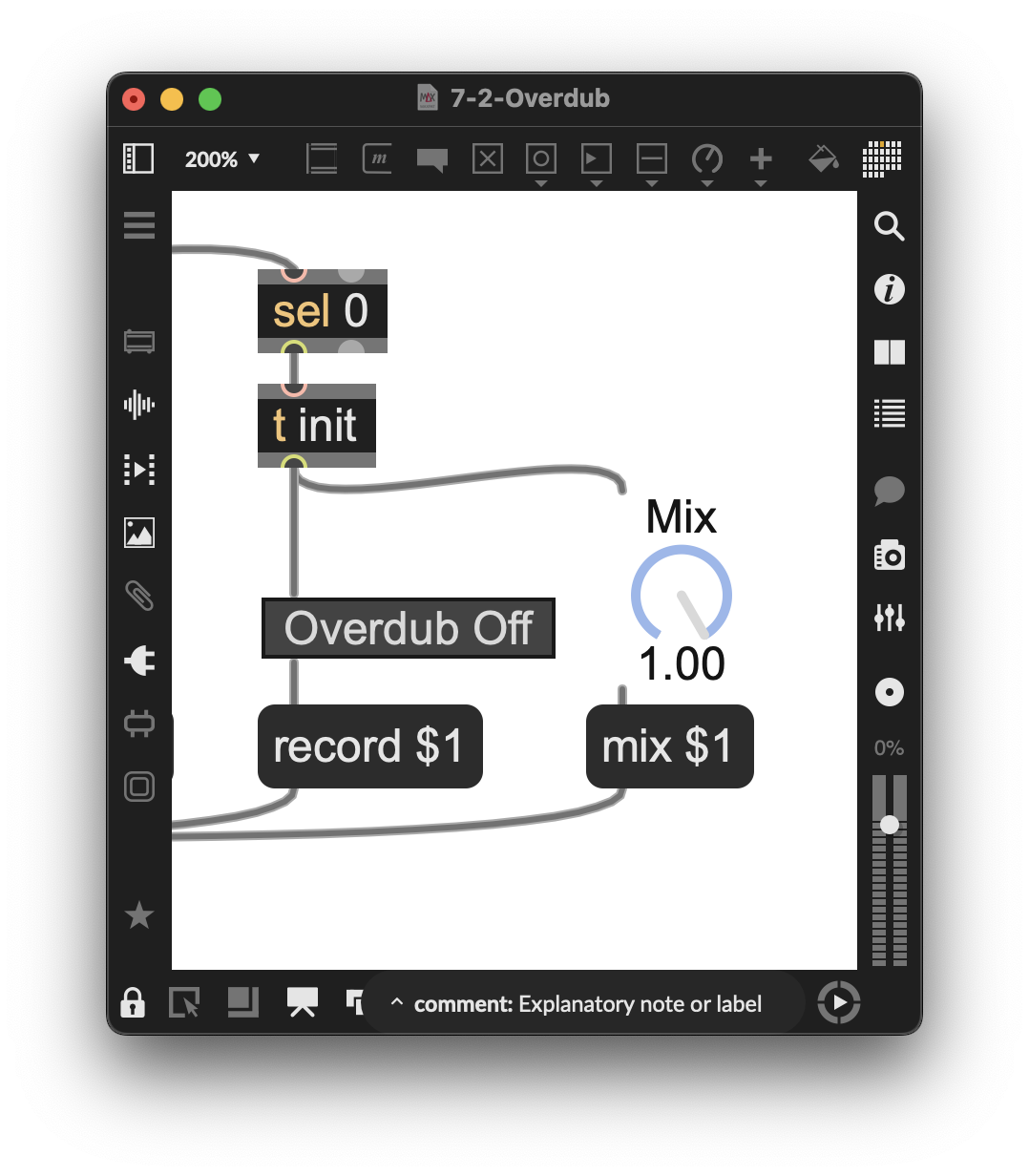
Figure 7-07
Declicking
(Example Patcher: 7-3-Declicking)
To enable declicking at the beginning and end of a loop, we again use the trapezoid~ operator to provide a signal ramp at the loop’s start and end. In this example, it uses the playback (loop) counter~ which is then scaled to phase (0. to 1.) to drive our *~ (multiple inputs) that create the ramp. The scale~, trapezoid~, and *~ objects are added after the peek~ and before the out~ operator. Finally, we’ll add two param objects to set how much ramp is used. To turn off declicking, set these values to 0. and 1.
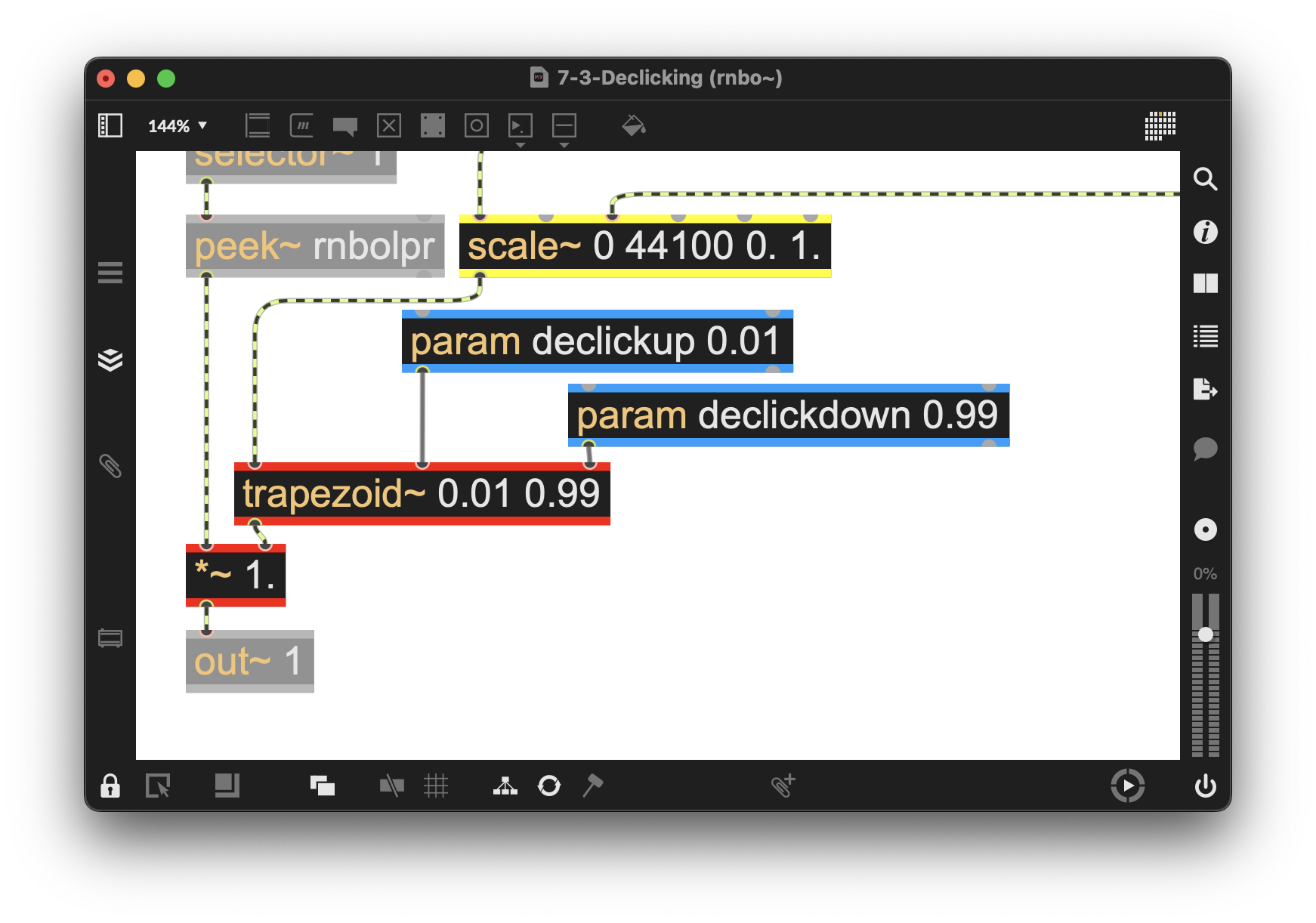
Figure 7-08
In our parent patcher, we have added two messages to control the new param operators.
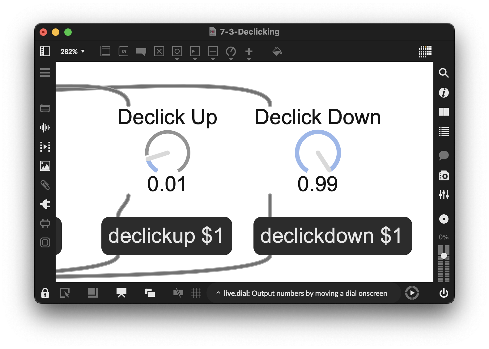
Figure 7-09
Speed and Direction
(Example Patcher: 7-4-Speed-Direction)
To add the control of speed and direction of our overdubbing, all we need to do is change the sig~ operator that controls the speed of the latched counter~ and get the same counter~ operator to count backward from the latched value.
We have added a param operator named “speed” to control the value of the sig~ going into our latched counter.
- A value of 1 is normal speed.
- A value less than 1 slows the playback.
- A value of 0 stops the playback.
- A value greater than 1 speeds up the playback.
One thing to keep in mind with speed changes: overdubbing is unpredictable and works best at normal speed.
For reverse, we use the !-~ to subtract the incoming counter value from the latched value, making it count backward.
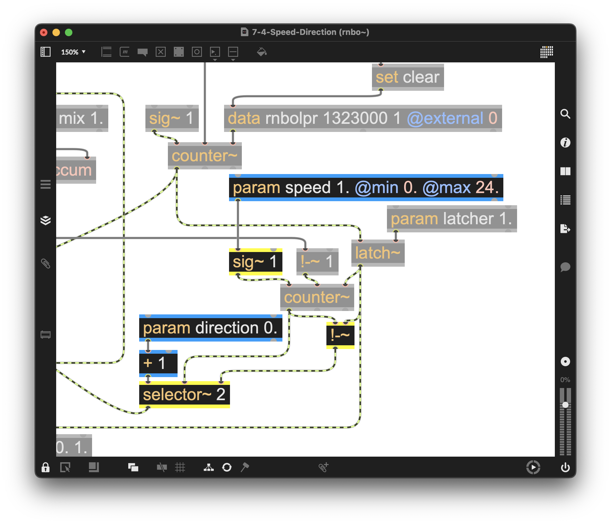
Figure 7-10
The trio of param direction 0., + 1, and selector~ 2 operators are used to set the forward or reverse speed to the counter~ operator that sets the speed (the counter~ operator’s selector~ operator input is also used for overdubbing). Note that attaching the !-~ operator is a handy way to set a negative value for the output of the counter~ operator.
Here’s how the updated speed and direction patching fits into our overall patcher:
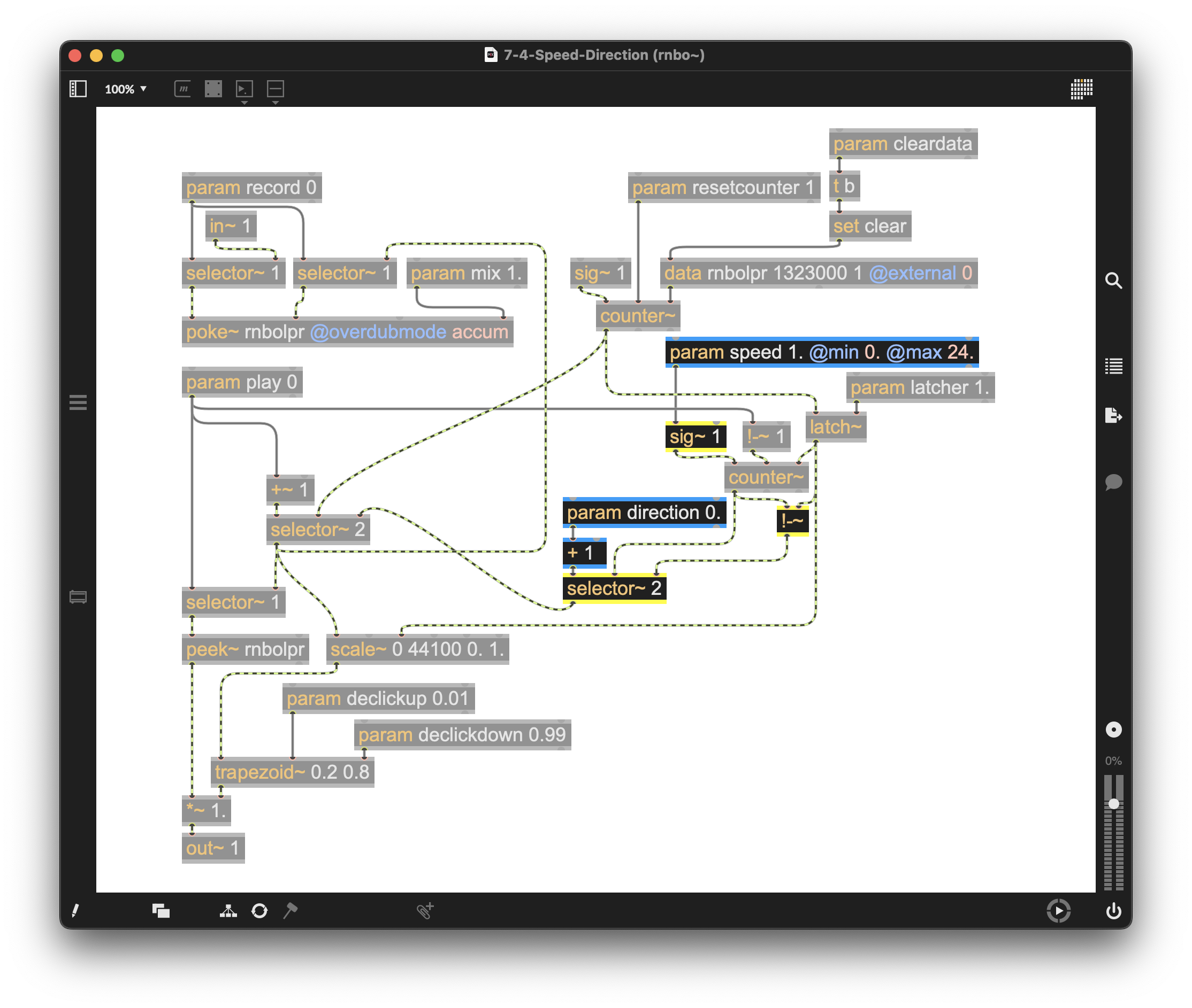
Figure 7-11
Now, let’s add the UI changes to our parent patcher to support the new speed and direction features:
We’ll add a live.tab object configured as a button and a message box object to send a direction 0/1 message into our rnbo~ object. To provide a UI for speed control, we’ll use a live.dial object, a message box ($1 150), and a line 0. object to construct a set of messages that smooth out speed changes to minimize the stairstep/ripping effect we’d typically hear. (If you like that sort of stairstep/ripping effect, just remove the message box and line objects!) And finally, another message box (speed $1) to set the speed of our recording and playback in gen~.
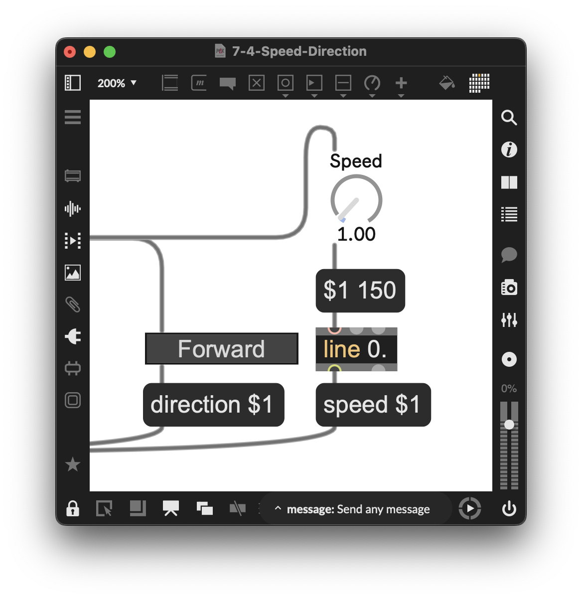
Figure 7-12
Creating a Performance UI
(Example Patcher: 7-5-Performance-UI)
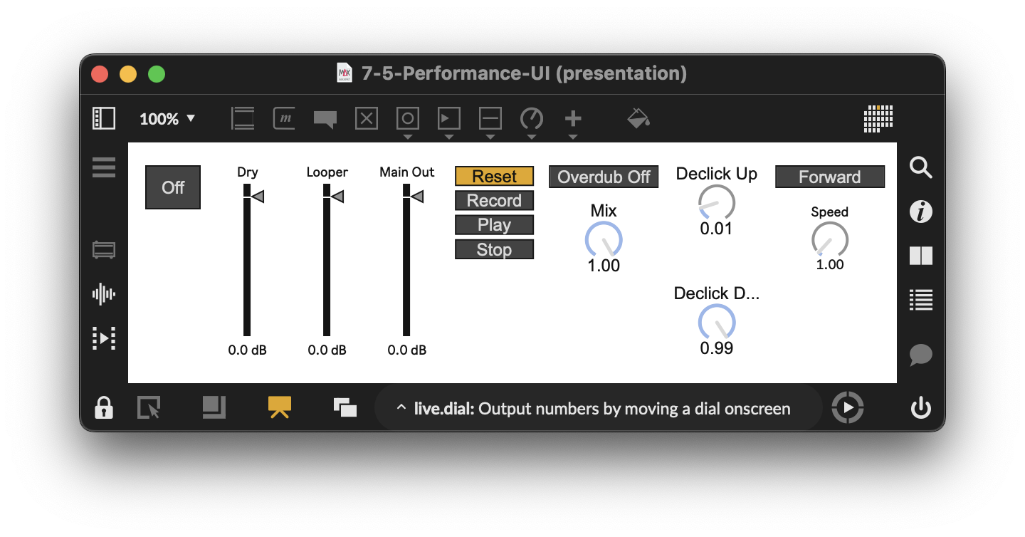
Here’s the final version of the parent patch. As before, you’ll notice the Live UI objects that were added to Presentation Mode by their salmon-colored outlines.
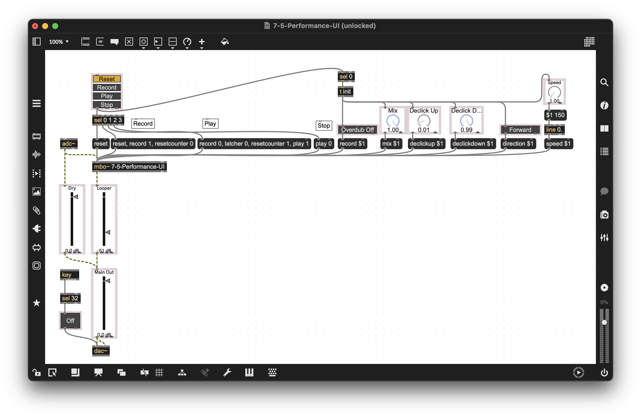
Figure 7-13
Finally, we’ve organized our UI in a meaningful way, and you can move them around as you’d like.