Chapter 2 — Multitrack Looper (Max)
Introduction
In this chapter, we will create a multitrack looper in Max with varispeed playback control and the ability to run multiple loops synchronously or asynchronously. In doing so, our multitrack looper will allow you to add as many or as few tracks/loopers as you desire and also enable the ability to process each track/looper individually. As we patch, we’ll explore the use of Max abstractions as a way to create individual tracks/loopers. You’ll see this technique used throughout the rest of this book.
Reset, Record, Play, Stop
(Example Patcher: 2-1—Reset-Record-Play-Stop)
Here are the basic elements we’ll need to create for this looper:
- The ability to record and store our loop
- The ability to play a stored loop back
- The ability to stop recording, set the end of the loop, and enable playback
- The ability to reset our looper.
To achieve this, we’ll use three MSP objects that will be the core of this patcher: a buffer~ object (to store what we record), a record~ object (to record input), and a groove~ object (to play the audio recorded).
Since recording, storage, and playback will all be working with the same audio material, we will use a named buffer~ object. Rather than being connected together with patch cords, the buffer object works by means of a shared name. A buffer~ is given a unique name (it must be unique), and both record~ and groove~ objects use that same unique name to access the buffer~ object. Record~ records the audio into the buffer~, and the groove~ object plays back the recorded audio from the buffer~.
But how much audio do we want to record? In addition to being assigned a name, the buffer~ object lets us set a maximum duration (in milliseconds) for our looper, along with the number of channels we’ll be using. For this example, we will be using a value of 60000 (1 minute in milliseconds). This number is arbitrarily high - while we will not always record a 60-second loop, we’ll “set aside” that much memory and use a timer to set a loop length equivalent to the length of the material we record. Our example patch will be recording in mono, so we set the number of channels to 1. By default, the record~, buffer~, and groove~ objects are set to 1 channel, but we’ll use arguments to explicitly set the channel count to provide us with a visual reminder. In the following example, you’ll notice that the buffer~ object uses arguments to set its name (lpr), its length (60000 milliseconds), and the number of channels (1). The following diagram illustrates how we used a shared name, along with the maximum length and number of channels set for the buffer~ object using arguments. You’ll see this used in patches throughout the rest of this book.
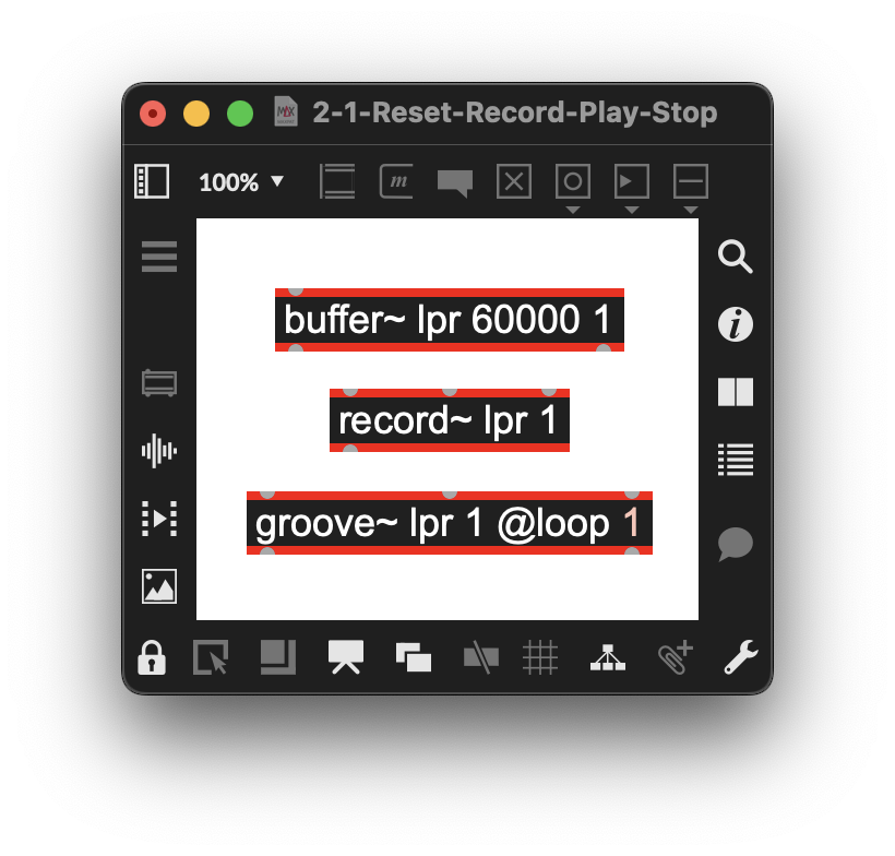
Figure 2-01
Now that we have our core objects set up, let’s consider the basic tasks we need to perform to control the reset, record, play, and stop operations, as well as the order in which these tasks occur.
We’ll start with how we’ll record audio input. That task is simple: we need to provide an input source for our audio, and enable/disable recording of that input. We’re going to use an adc~ object as our live input source (just as we did in the previous chapter), and connect it to the record~ object. Turning recording on and off can be done in several ways, but we’ll keep it simple this time and add a toggle object that sends a 1 or 0 to enable or disable recording.
If you’d like to test your patch, you can use the setup shown in the following figure. Add the objects, connect them as shown, lock your patcher, turn on the patcher with the toggle attached to the adc~, and record something short by using the toggle attached to record~. When you’ve stopped recording, double-click the buffer~ in your patcher. You’ll see what was recorded in a pop-up window that shares the name of the buffer~.
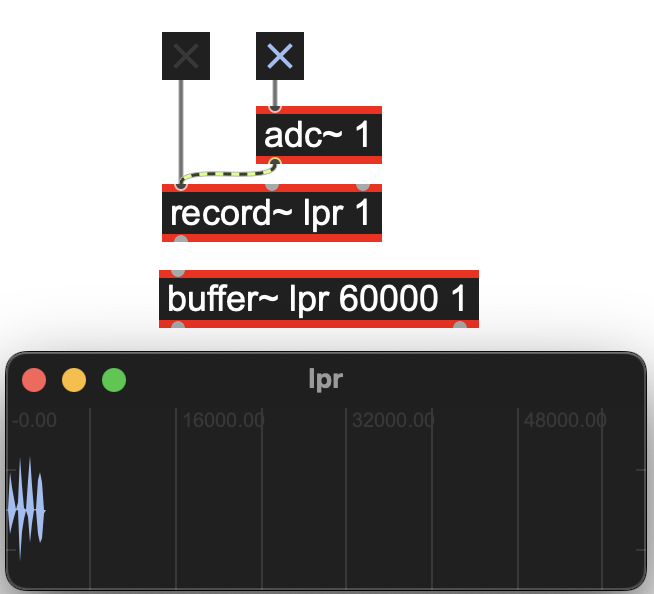
Figure 2-02
Setting up our patch to do playback is a bit more complicated. We’ll need to implement a timer that allows us to set the endpoint for our recorded loop. For these examples, we’re assuming that we’ll start recording at the beginning of the buffer (0). We’ll do this by creating a timer that we’ll start running when we begin recording. When we stop recording, we’ll stop the timer and use the value of the elapsed time of the recording (in milliseconds) as the endpoint for our loop in groove~. That way, we only playback and loop the part of the buffer~ that we recorded into. Since we’re using the timer output, we don’t need to worry about any additional space in our buffer. This additional space allows us to create loops of varying durations up to the maximum of the buffer~..
The Max timer object is just what we need for this task. Sending a first bang message to the object’s right inlet starts the timer, and sending a second bang message to the object’s left inlet outputs the value of the elapsed time between the two bang messages. This value then goes into the rightmost inlet of the groove~ object to set the loop length.
To play our loop with groove~ we need to do a few things:
- We tell the groove~ object what speed to play the audio back by providing a signal-rate value using a sig~ to the left inlet of the groove~ object. A value of 1.0 is normal playback speed. We can also change this to other positive floating-point values. Values greater than 1.0 speed up playback, values between 1.0 and 0 slow playback down, and negative values have the same effect, but the playback is in reverse.
- Sending the message “startloop” to the right inlet of the groove~ object starts the loop, and the message “stop” stops loop playback.
- We will enable the playback to loop by adding the attribute @loop 1 as an argument to the groove~ object. By default, the groove~ object has looping disabled (it defaults to @loop 0).
We’re ready to start setting up the control portion of our patch. Let’s review the four basic controls for our looper: reset, record, play, and stop.
To reset our looper requires the following sequence of actions:
- Stop playback
- Stop recording
- Reset the timer. (We use a new object named onebang, more on this later.)
- Clear the buffer~
- Make sure the playback speed is set to 1.
Setting our looper to record requires the following sequence of actions:
- Stop playback
- Clear the buffer~
- Start the timer
- Start the recording
Playing back our looper requires the following sequence of actions:
- Stop the recording
- Stop the timer and use that value to set the maximum value for the timer (the loop maximum)
- Start the loop with “startloop”
Stopping the loop is simple:
- Message “stop” to groove~
The actions listed for each mode of operation should happen rapidly, and in the sequence you’ll see above. To accomplish this, we’ll use the trigger object (whose name is often shortened to t). The t object is a go-to object in wide use and one of our favorites for good reason—it takes a single bang message as input and outputs multiple messages, symbols, integers, floats, bangs, rapidly from right to left, one after the other.
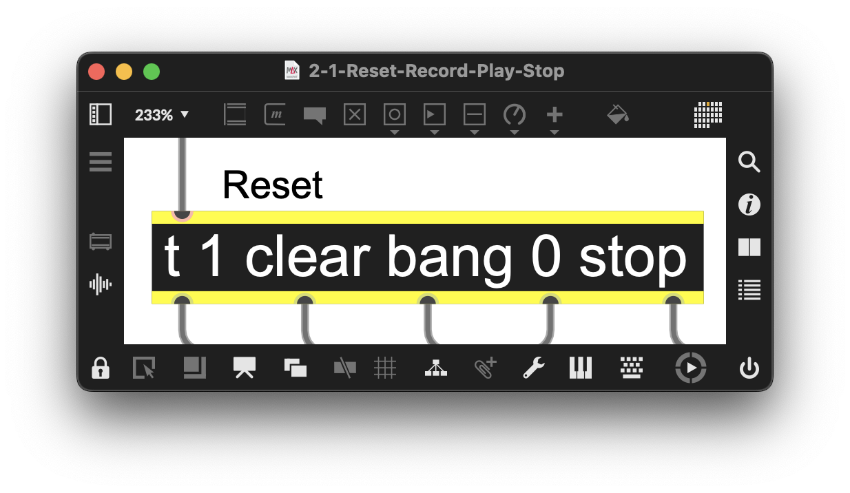
Figure 2-03
In the above example, we have created a t (trigger) object with a series of messages and integers associated with the actions listed above. A single bang message will output these in order, right to left. For example, here are the five things that must happen for reset. Compare them to the figure above:
- A stop message to groove~ object stops playback
- A 0 message to the record~ object to stop recording
- A bang message resets the timer,
- A clear message clears the contents of the buffer~ object
- A 1 message resets our sig~ (playback speed) to normal playback
The arguments to the trigger object for recording are arranged in a similar fashion. For record, right to left order:
- A stop message goes to the groove~ object stops playback
- A clear message clears the contents of the buffer~, object
- A bang message resets the timer
- A 1 sets the sig~ to normal playback speed
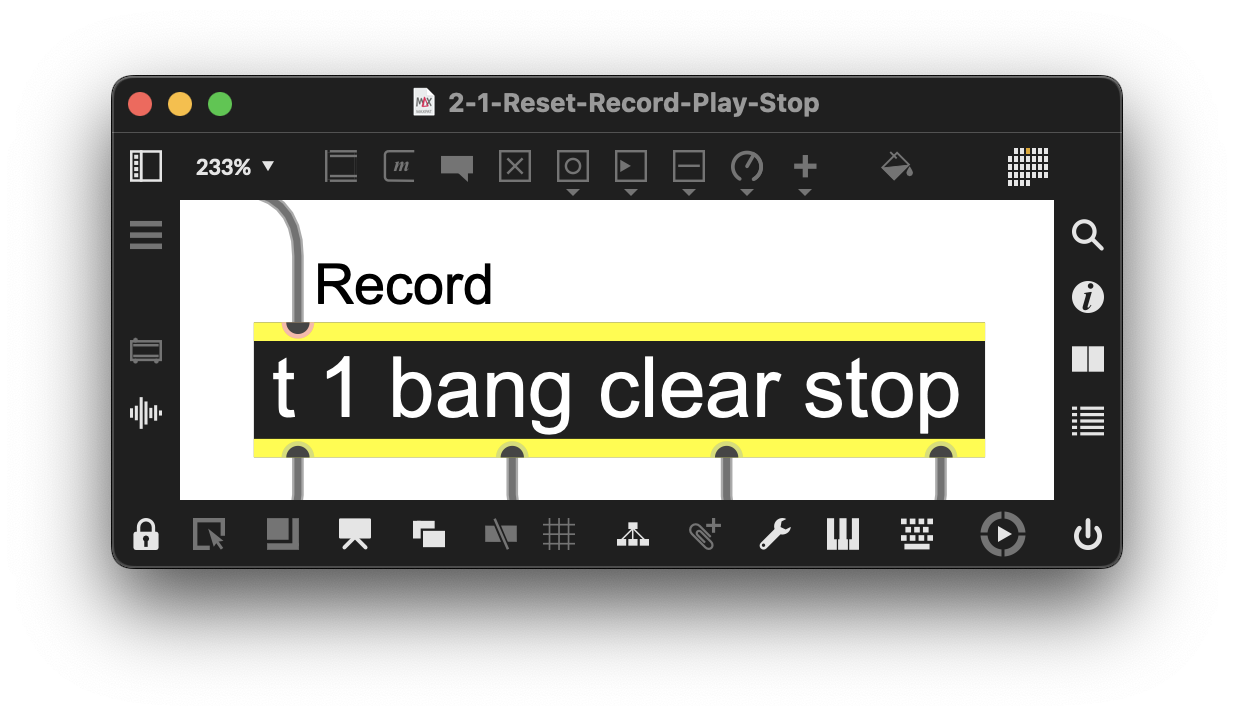
Figure 2-04
The arguments to the trigger object for playback are arranged similarly for playback, in right-to-left order:
- A 0 message to the record~ object stops the recording
- A bang stops the timer and sends the elapsed time to set the loop time for the groove~ object
- A startloop message to the groove~ object starts playback
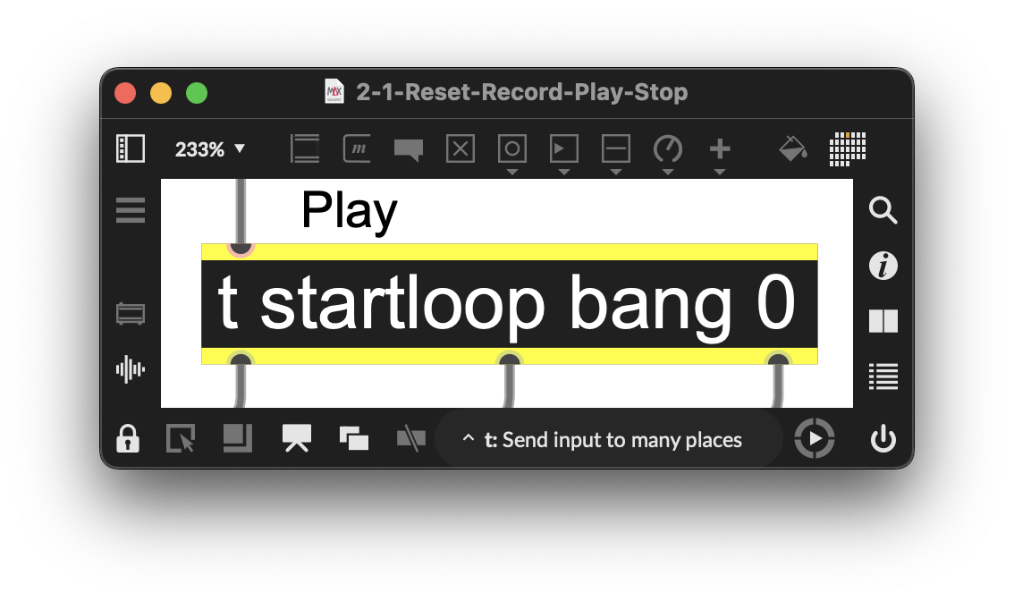
Figure 2-05
Stopping playback requires a single stop message to the groove~ object.
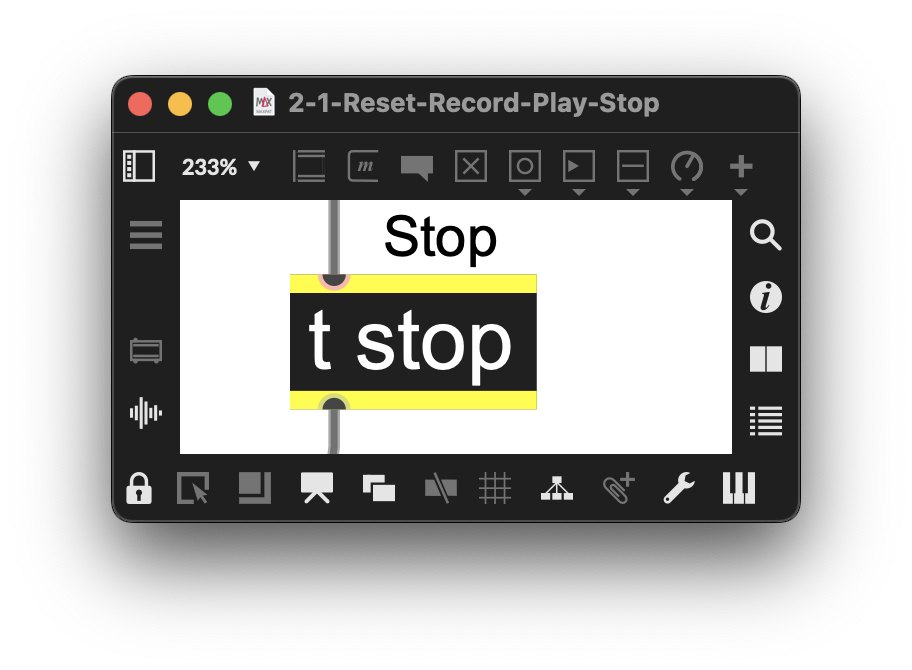
Figure 2-06
If you look carefully, you’ll notice that the patcher contains an object you may not have seen before, called onebang. There is a subtle bit of patching here that needs some explanation. It starts with the question: What if we want to be able to click play to restart after stopping, but without resetting the timer?
This is a perfect example of why the onebang object exists. If you look carefully, you’ll notice that both the trigger objects that control play and reset send bang messages to the timer object. Our problem is that we want to avoid resetting the timer if we move between stop and play. Unless we take action, the timer will always reset when we restart our looper after pausing it.
The onebang object does something really subtle that solves our problem: it acts like a gate object in Max that works with bang messages. Sending a bang message to the first inlet will only be passed through the object after a second bang message is sent to the right outlet. By adding the onebang object, resetting our playback will send the bang message that “opens” the onebang object, allowing the bang message to pass through again. However, until then, the play trigger device will still be able to pass through without resetting the timer.
As we build our user interface, we’ll use objects that you’ll be familiar with by now. We will use a live.tab object with four tabs to act as buttons (Reset, Record, Play, Stop). These are set using the live.tab object’s Inspector and use a select (sel) object to route specific bangs associated with each index number for the tabs (0 for Reset, 1 Record, 2 Play, 3 Stop) to each trigger object.
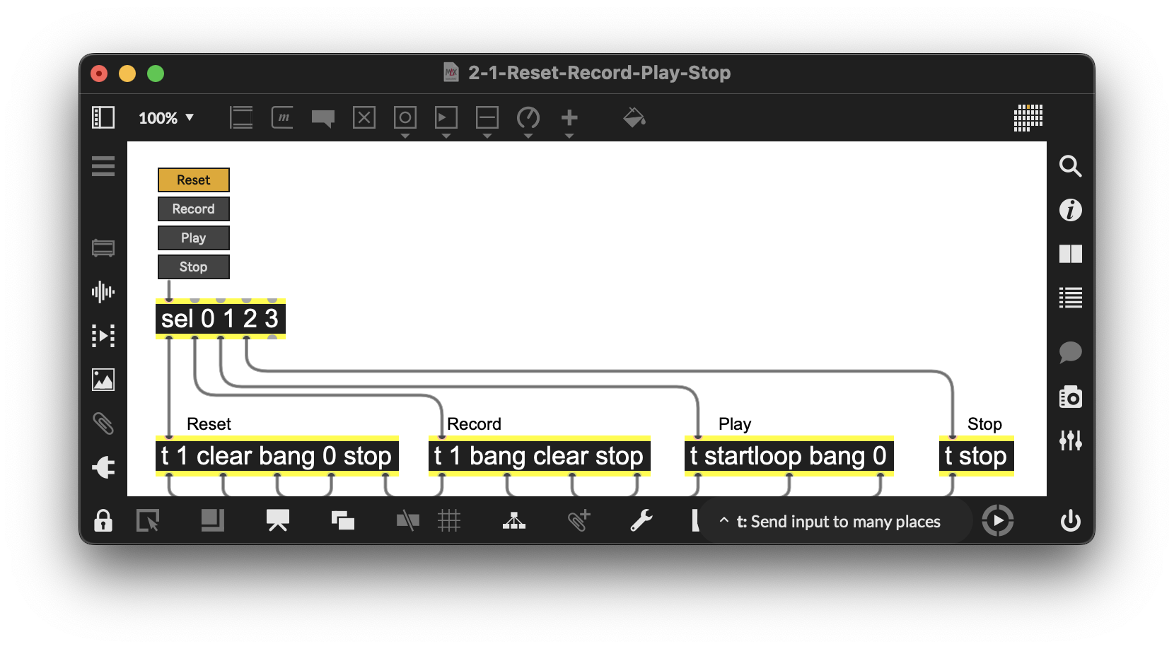
Figure 2-07
So far, we have worked to avoid patches that are difficult to read. However, as our patches become more complex, we’ll need to find ways to make our patching easier to read.
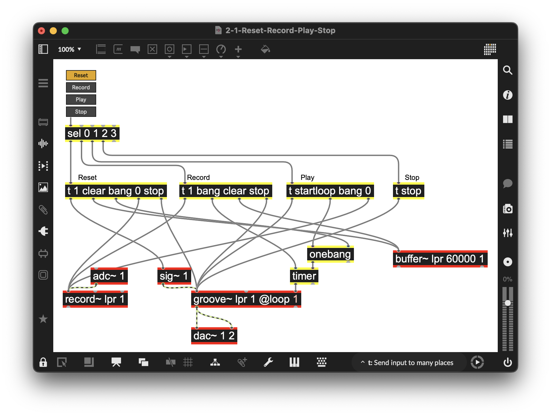
Figure 2-08
The messages, routed from each trigger to their intended destinations, can become visually chaotic. At this point, it’s a good time to select all the patchcords and align them using Auto Align or Route Patchcords in the “Arrange” menu of Max. Either command will get it close, and then you can manually clean it up to suit your needs. You might also consider coloring the patch cords in their Inspector to create visual flow. At some point, we realize that any complexity in a visual coding environment might start to look…daunting. One method of making it easier to trace the working of a patch is by aligning the patch cords and objects. Later in this chapter, we will examine encapsulation and abstraction—features of the Max environment that will help streamline and refine your patching. In the meantime, here’s what our patch looks like:
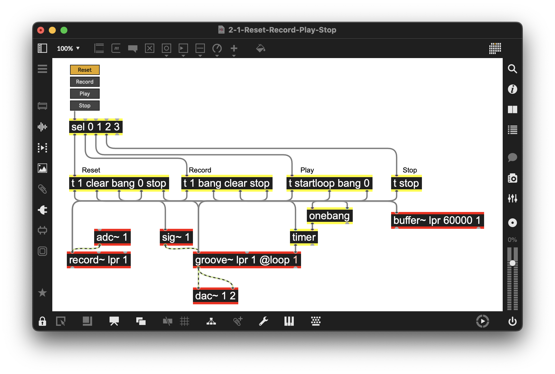
Figure 2-09
Speed/Direction Control
(Example Patcher: 2-2-Speed-Direction)
We’re now ready to add two new features to our looper: control over the speed and direction of recording and playback. Controlling the playback speed is a relatively simple change to make. Since we’re using a sig~ object that outputs its value at signal rate. We can add a live.dial object attached to our sig~ object that allows us to smoothly change the playback rate. As we said before, sending positive numbers greater than 1. to the sig~ object speeds groove~ playback up, and numbers between 1. and 0. slow it down. Negative numbers reverse the direction. -1 runs groove~ at normal speeds but backwards, numbers less than -1. speed it up, and numbers between 0. and -1. slow it down. So we actually have control over both the speed and the direction of playback. We’ll add a live.dial object and use its Inspector to change its name to “Speed/Direction,” and set its initial value (under Initial Enable) to 1 and its range from -5. to 5.
We’ll want to smooth out changes in our input to the sig~ object, so we have also added a line object to handle the smoothing. (Remember to add an argument of 0. to the line object, since we’ll want the output to be a floating-point value rather than the line output’s default integer output.) And finally, we’ll add an argument of 1 to the sig~ object so that the default playback state is forward at normal speed.
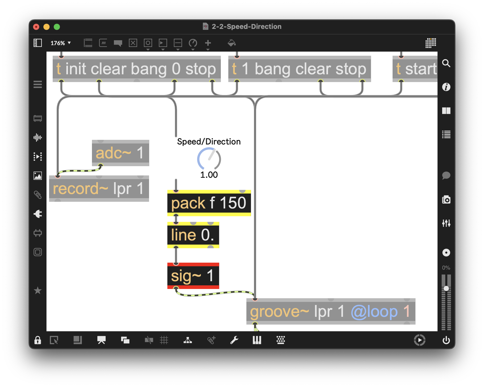
Figure 2-10
Declicking audio output
(Example Patcher: 2-3-Declicking)
One of the challenges to recording and manipulating audio loops involves handling clicks that occur at the beginnings and ends of loops. There are many ways to deal with this (that’s often the case with Max). We’re going to show you an easy way to do this by adding a quick volume ramp from 0. To 1. at the start of what we’re playing back and add a corresponding ramp from 1. to 0. at the end. The trapezoid~ object provides us with a way to do just that, and to do it in sync with the audio playback from the groove~ object.
But how do we ensure that we can set a ramp based on the loop length the groove~ object is working with? The groove~ object is all set up to help us with that, using its right outlet. Whenever the groove~ object cycles through its loop, it outputs a signal-rate ramp that goes from 0. when the loop starts to 1. when the loop ends. In turn, the trapezoid~ object is set up to create its output from exactly that kind of signal-rate input, which means that we don’t need to worry about how long our loop is—the two objects work together to handle the heavy lifting.
So all we need to do is connect the right outlet of our groove~ object to the inlet of the trapezoid~ object, and take the resulting ramp from the trapezoid~ object and use that to control the amplitude of the groove~ object’s left outlet using a *~ object. And just in case you’re wondering how steep the ramps output from the trapezoid~ object are, we can set them by adding a pair of live.dial object (with names and with their initial values of .01 and .99 set using their objects’ Inspectors) connected to sig~ objects to allow us to adjust how steep the beginning and ending ramps are.
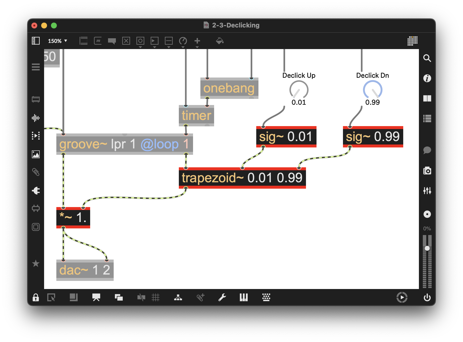
Figure 2-11
Reducing Visual Clutter: Encapsulation
(Example Patcher: 2-4-So-Far)
Here’s a look at our patch so far with the new features added:
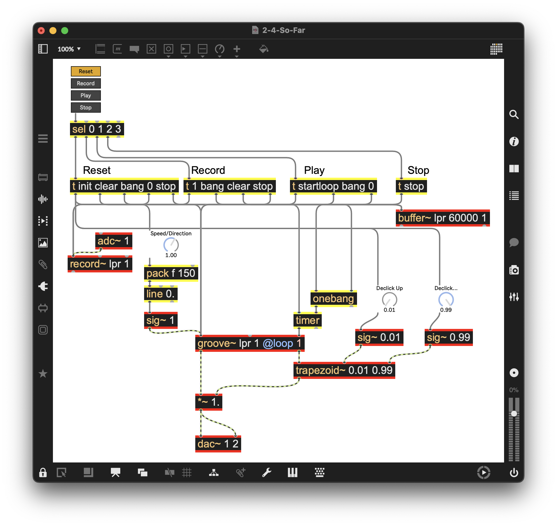
Figure 2-12
Since the subject of this chapter is multitrack loopers, the patch you see will become one track of our looper. You can imagine how complex our patch will look if we multiply this by n number of tracks. How can we streamline our patch as we duplicate it and still make it easy to work with?
One way to clean up a patcher is to use Max’s “encapsulate” function (you can find the function under the “Edit” menu in Max), which takes the objects you select and automatically creates a Max subpatcher that contains what you’ve selected. The created subpatcher automatically adds inlet objects where needed and outlet objects as well. Here’s how to automatically encapsulate a portion of our patch, including the creation of these inlets and outlets.
To prepare our patch for encapsulation, take a look at the UI objects that we’ll want to access outside of our new subpatcher. In this case, UI elements, as well as the adc~ and dac~ audio input and outputs. Visually group them together. In the following example, below you can see that we moved objects that will send information into the subpatcher to the top of our patch, and those that will receive information from the subpatcher to the bottom. The live.dial objects both send and receive data, so we’ll put them above, too.
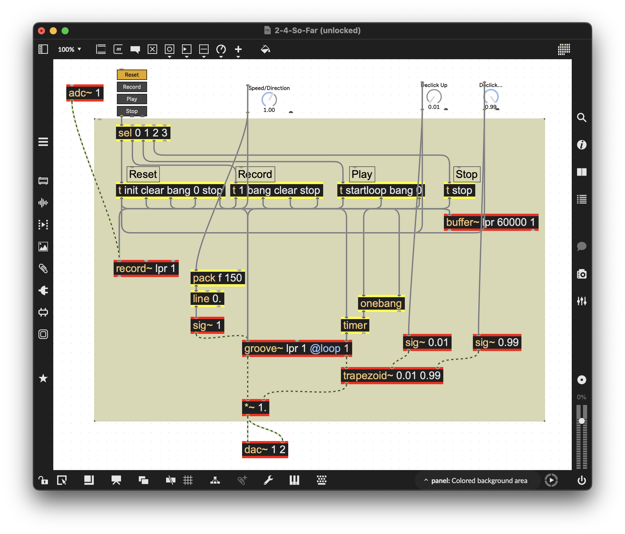
Figure 2-13
The resulting patcher elements in the middle (shown in the yellow/grey area)are what we want to include in our subpatcher. Click and drag to select those objects, and then select “Encapsulate” from Max’s “Edit” menu. You should now see something like this:
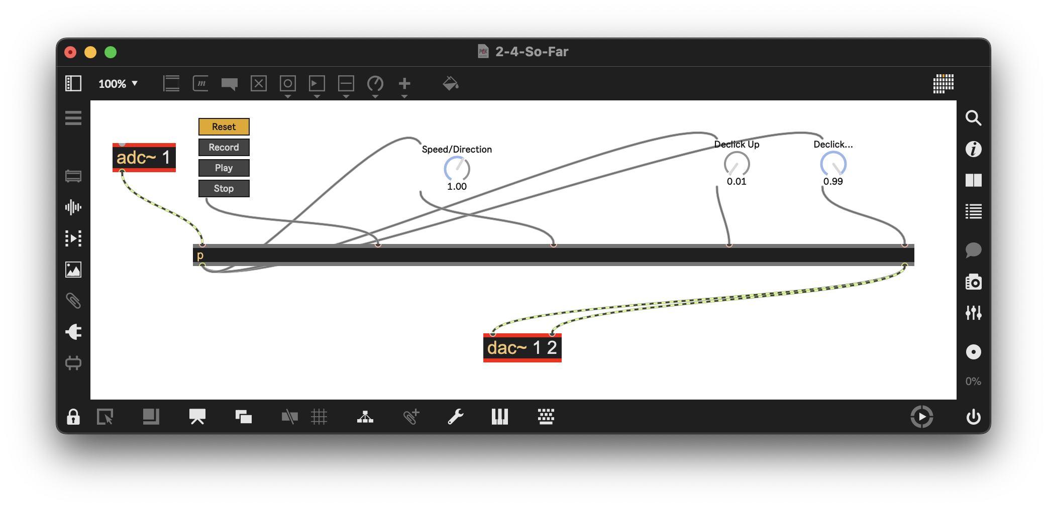
Figure 2-14
In your locked patcher, double-click the newly created p subpatcher to see its contents:
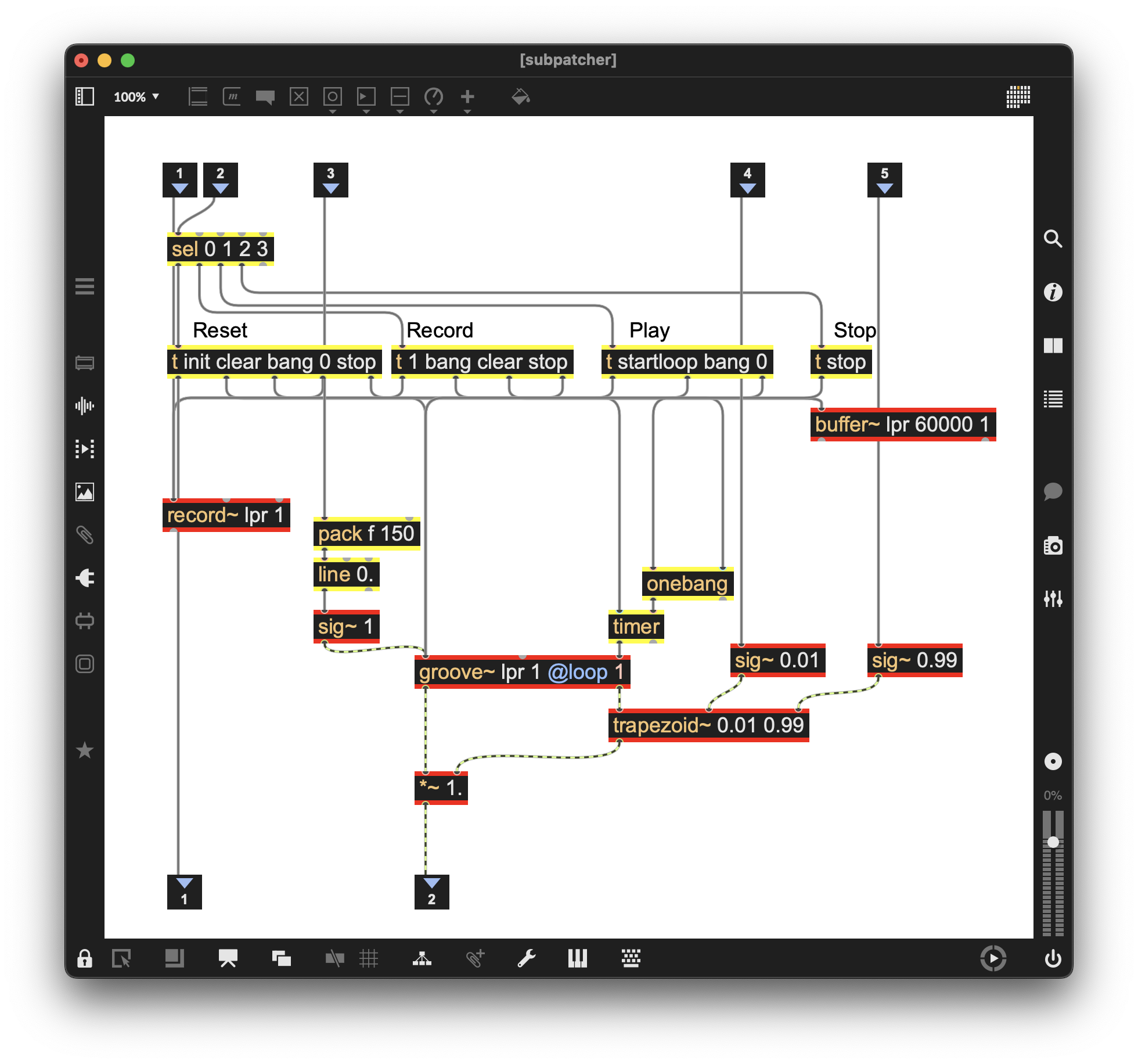
Figure 2-15
You’ll see numbered square objects at the top and the bottom of the subpatcher. Encapsulation automatically adds these inlet and outlet objects, numbered automatically from left to right. You can rearrange the inlets and outlets for greater clarity (for example, we want to have our audio input and output on the far left of our subpatcher)—they’ll automatically renumber themselves, and the position of inlets and outlets will also change in the parent patch. Here’s the new order we’re using for the subpatcher:
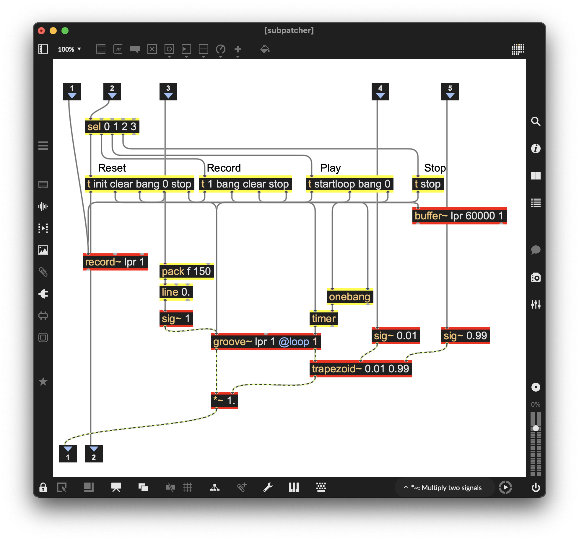
Figure 2-16
Here’s the result of the rearrangement in the parent Max patch (we’ve resized the p patcher, too):
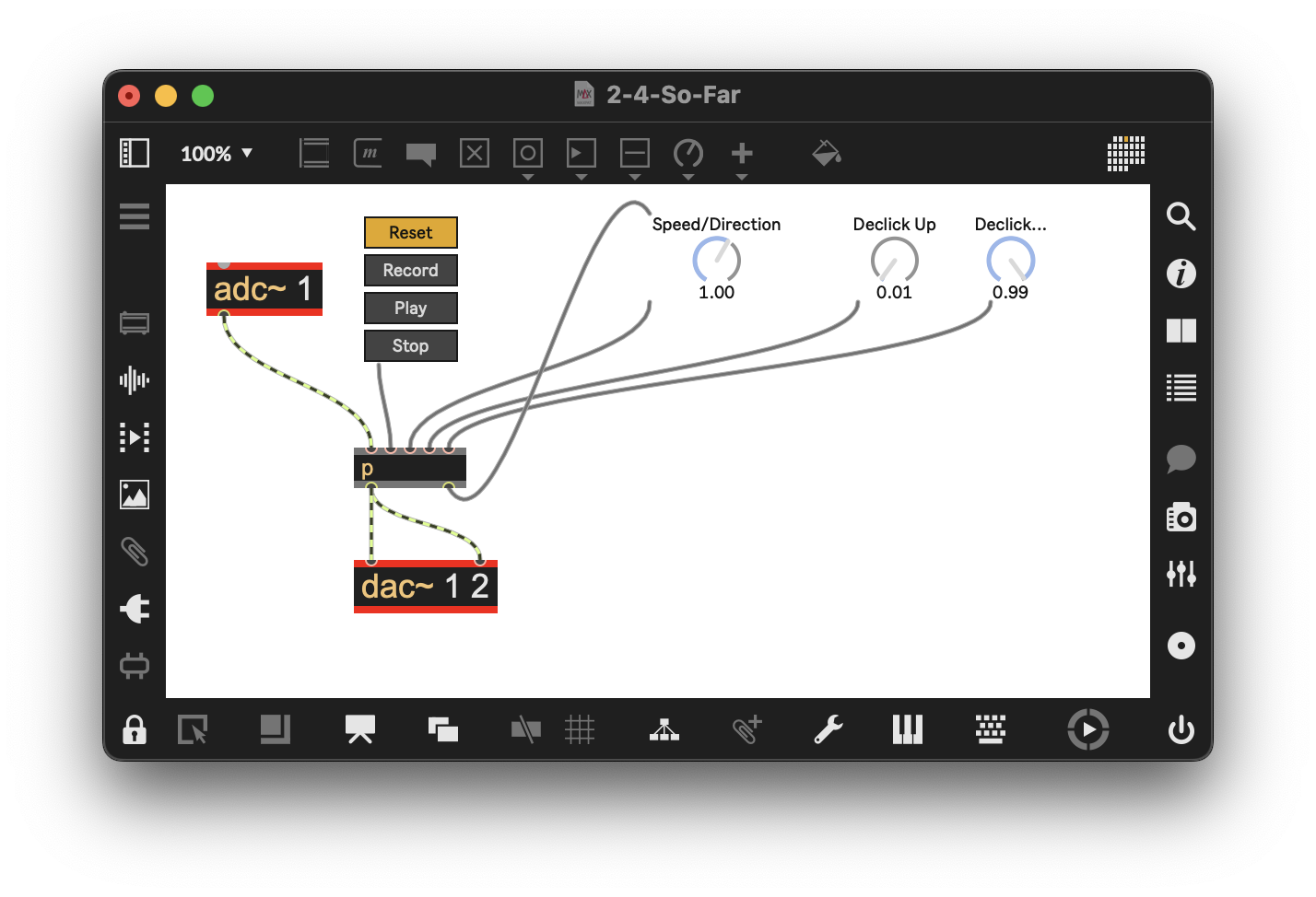
Figure 2-17
The result is smaller and easier to read.
From encapsulation to abstraction
(Example Patcher: 2-5-Abstraction)
You might think that creating multiple tracks for our multitracker looper simply requires copying and pasting as many instances of the patcher we just encapsulated as needed. But it’s not quite that simple.
You’ll recall that the trio of buffer~, record~, and groove~ objects we created share a single unique name. If we copy our newly encapsulated patch, the trio of objects in the copy will still retain the same names as in the original, so they will not record/play different material. Fortunately, Max has a solution to this problem of assigning a unique shared name to each copy.
But first, we have a little preparatory work to do:
- Save the main patcher with a unique name in a folder.
- Double-click to open the p subpatcher in your main patcher.
- With the sub-patcher opened and at the front of all other patchers (important)…
- Select “Save As…” in the File menu and save the p subpatcher in the same folder as your main patcher—give this new file a unique and memorable name. For this example, we’ll use lpr-abs as an abbreviation for “looper abstraction.”
After saving the p patcher with a new name, return to your main patcher. In the object box of the p subpatcher, rename it by entering the name of the subpatcher you just saved (lpr-abs). You can omit the “p” prefix at this point. When you hit return, Max will load the lpr-abs file you saved in place of the original p patcher.
Congratulations! You have successfully created a Max abstraction—an element of Max patching that behaves like an external object, except that you can access and edit its contents by double-clicking the object’s name.
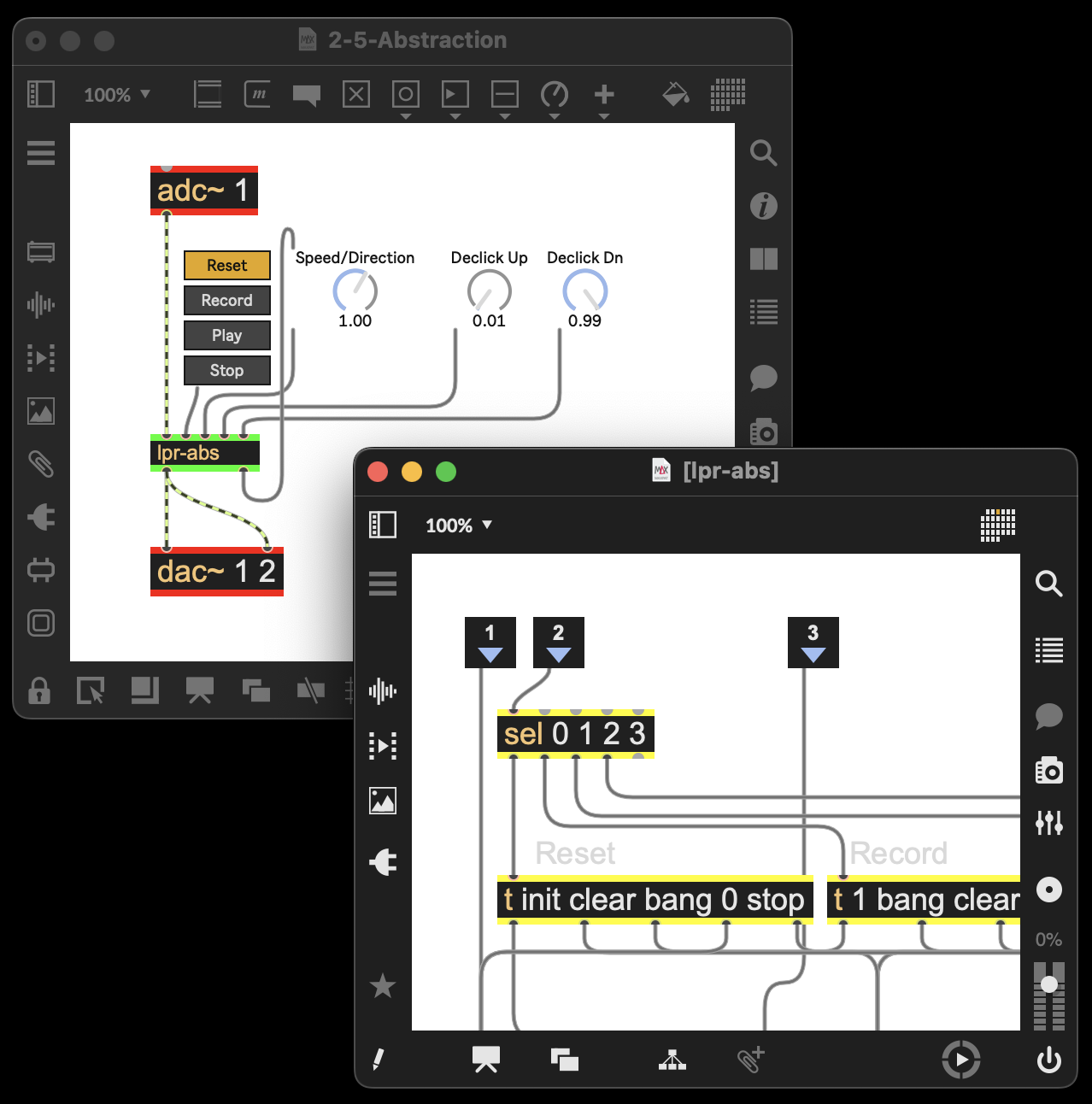
Figure 2-18
This is a very handy feature when creating a patcher that you’ll reuse in multiple places within your patcher or in other patchers. When you edit the original saved abstraction, you’ll change all instances of it, which saves a lot of time and energy. In fact, any of your patchers can be loaded into an empty object by typing in the name of the file, just as if it were a native Max object, as long as they are in the same folder as you’re currently working in—hence the creation of a folder. There are other ways to handle Max’s ability to find abstractions, including adding custom search paths and Projects, but for now, we’ll use the folder method.
So, we now have a great piece of reusable patching, but we still need to address the fact that our abstraction’s record~, buffer~, and groove~ objects still reference the same buffer name (lpr).
Max abstractions have a special feature that allows us to generate unique names for our buffer and the objects that reference it. If you add the 3-character string #0_ (pound sign zero underscore with no spaces) to the beginning of the shared name objects inside your abstraction. Once we’ve done that, all instances of the #0_ in the saved abstraction will have a unique numerical identifier generated for the character string that will be added every time that abstraction is loaded, with a different one for each abstraction. In the following example groove~,buffer~, and record~ in the patcher have been renamed with #0_lpr.
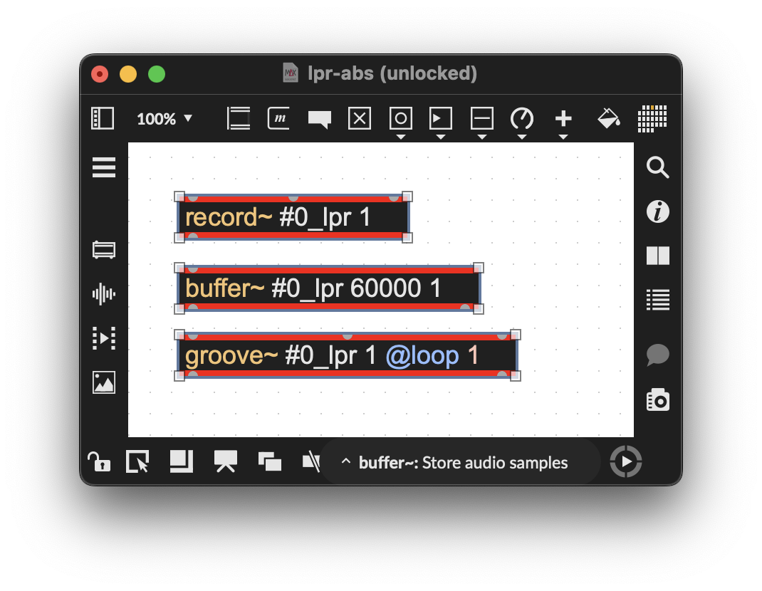
Figure 2-19
We can now load different copies of the abstraction, and when you open the abstractions, each copy will have its own unique shared name (the number that identifies the unique names is handled internally by Max and cannot be controlled). Please note that the underscore is not strictly required by Max, but we like it as it provides some visual space between the name and the unique identifier.
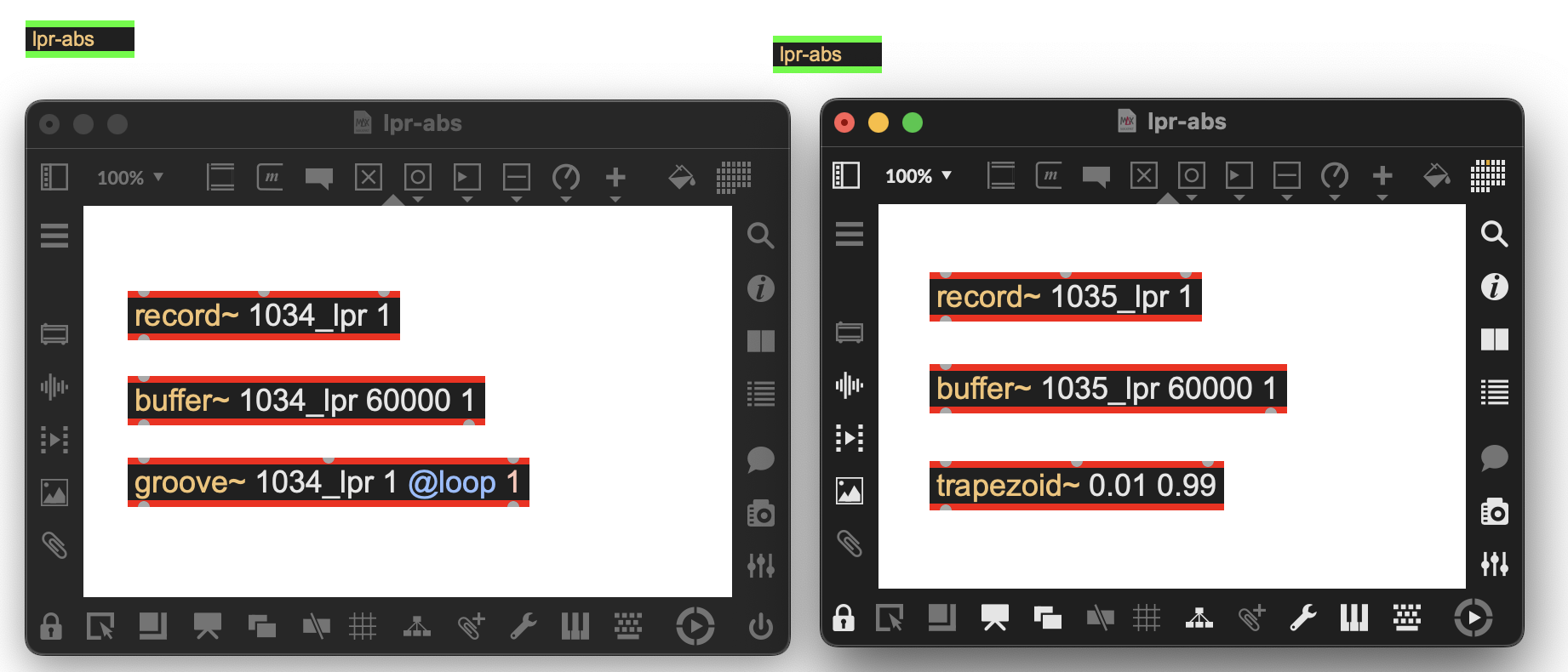
Figure 2-20
Here’s what the abstraction patcher looks like with the added #0_ character strings to the record~, buffer~, and groove~ objects:
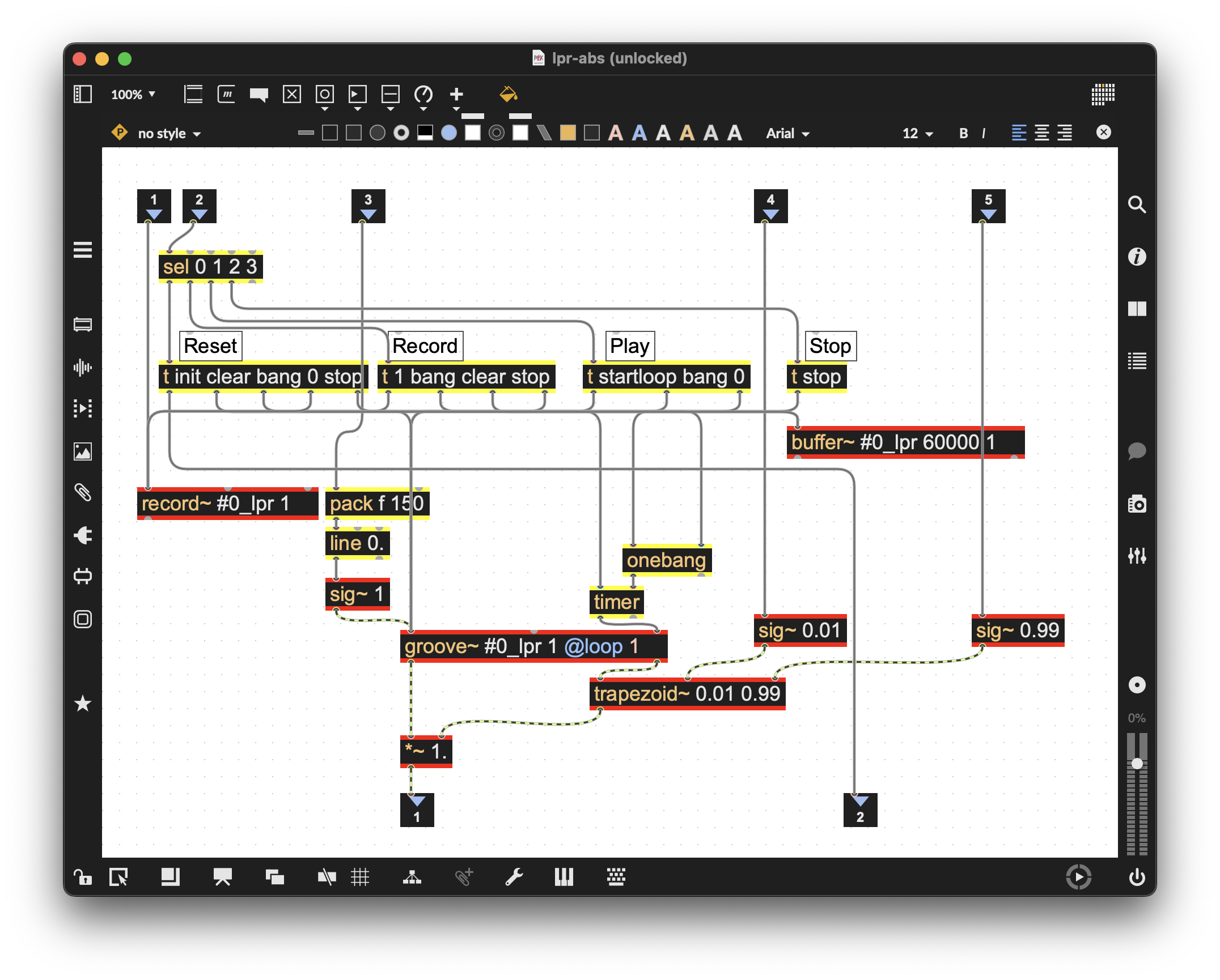
Figure 2-21
To track the functions of our abstraction’s inlets and outlets, we can add a “Comment” to each of them using the Inspector. After we’ve done that, we will get a pop-up message that tells us what each inlet or outlet goes to, or comes from, like this:
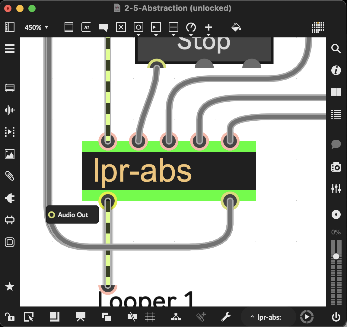
Figure 2-22
As we did in our previous chapter, add some live.gain UI objects, our spacebar on/off, and clean things up.
We now have a four-track, asynchronous looper perfect for experimental, ambient, and other musics.
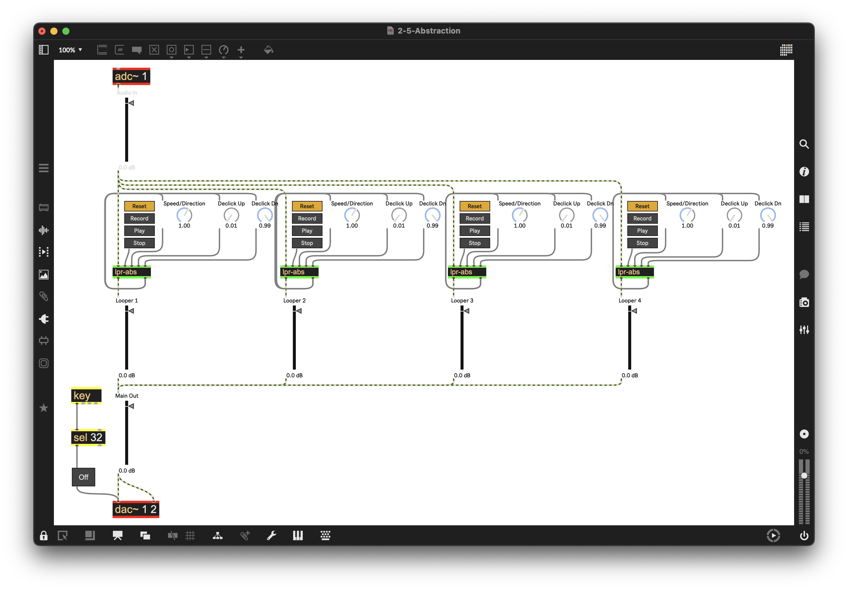
Figure 2-23
Synchronization
We now come to the trickiest part of our multitrack looper—synchronization. While you might think that syncing recording and playback of our multiple loopers sounds like it should be easy, it’s a challenging problem, and one that we’ll return to in different forms in our later chapters, where we’ll be looking at the gen~ and rnbo~ objects’ patching abilities. We will present one possible solution in the vanilla Max programming environment in this patcher.
For synchronization (the alignment of the beginning and end of loops when recording and subsequent playback), we will need a shared source of timing. For this example, we will start by creating the primary looper abstraction, which provides the timing data, and then modify the secondary looper abstraction as needed to synchronize with the primary looper.
In this chapter’s patcher, we’ve used the groove~ object, which outputs a sync signal for synchronization with several objects. We used this feature earlier when adding a declicking control. For our secondary loopers, we can substitute the MSP wave~ object for playback instead of groove~. We then use the “Loop Max” from the timer and sync output from our groove~ object in the primary looper to sync all the wave~’s in our secondary loopers. (At the time of this writing, there are no Max objects for recording audio that can be controlled directly by this signal from the groove~ object.) There is an object, poke~, that can be controlled by receiving an index (location by sample) to record, and peek~ can use a counter, but both of these options would require some translation of the sync output of groove~, which is phase (0.-1.). Such a translation would introduce other challenges that might be a bit of a rabbit hole at this stage of our development.
The approach we’ve taken in this patch is to automate the start of the recording at the very beginning of the loop’s playback in our primary groove~ (0. from the sync output). We then automatically end the recording when the loop wraps back around to 0. This is relatively simple to achieve, with the limitation that the action of recording will only be in sync if recording happens at normal speed. The reason for this is that the record~ object has no input control that takes into account any variation in speed or direction; it always records at normal speed. After that, playback will remain in sync with any changes to playback speed or direction from our primary looper. (You can still record at other speeds and directions, but the results will be unpredictable, which you might—or might not—find delightful.)
To create our primary looper, we need to set up one version of our looper abstraction that sends information to sync our secondary looper abstractions. We’ll send the sync output of the groove~ and the endpoint (Loop Max) value we get from our timer object from our primary to our secondaries. We’re going to add two additional outlets to the original patcher abstraction and save the result as our primary looper. It’s a simple addition: we open up the lpr-abs abstraction and add two outlet objects in between the preexisting outlet objects. To the outlet number 2, we connect the “Loop Sync Out” from the groove~ object, and to outlet number 3 we connect the output of the timer object. I named outlet 2 “Sync Out” in the Comment in its inspector, and outlet 3 “Loop Max.” Here’s what our primary looper looks like now:
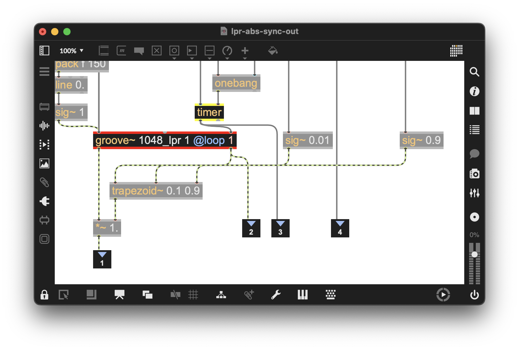
Figure 2-24
We now save this modified abstraction with a new name (lpr-abs-sync-out). This abstraction will serve as our primary looper, which we will refer to as “Looper 1” in the patcher. The other loopers will be secondary and identified by their respective numbers.
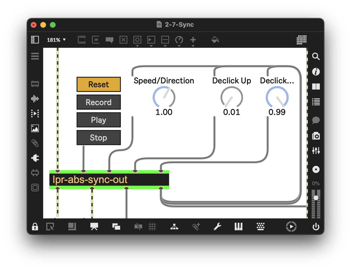
Figure 2-25
Secondary loopers
(Example Patcher: 2-6-Wave)
(Example Patcher: 2-7-Sync)
Since our secondary loopers will receive sync and loop endpoint information from our primary looper, they will have a reduced set of functions in their abstraction. We won’t need a timer output or speed/direction in the secondary loopers, as they will receive that information from our primary looper. Our patching will need to focus on different ways of recording and playing.
The playback part is straightforward. In place of the groove~ object, we can use the Max wave~ object to access our buffer~. The wave~ object plays back audio stored in the buffer~ object by means of a floating-point value at signal rate between 0. And 1. That means we can connect the sync outlet of our groove~ object in the primary looper to indicate which part of the buffer~ to play back in the secondary looper. We will also use the “Loop Max” from the timer output from our primary looper to set the end of the loop in any and all secondary loopers using the third inlet to wave~ called “Ending Table…”. When it receives this signal from our primary looper, it will play at the speed and direction specified by the shared sync signal. When there is no signal, the wave~ object will not play.
Things are a bit more complicated when it comes to recording. The solution we’re going to use can be found under the tab called “sync” in the groove~ object’s help file. It shows us a way to tell when the groove~ object loops back to the beginning using three objects: (delta~, <=~, and edge~). Used in combination, they detect when the input ramp from the groove~ object drops back to 0. and sends out a bang message at that time. Since we’re dealing with a loop, 0. is both the start of the loop and also signals the end, as well. (You may want to save that humble trio of objects as an abstraction—there are a lot of Max patching situations where you’ll want to trigger something based on the wrap of a ramp signal.)
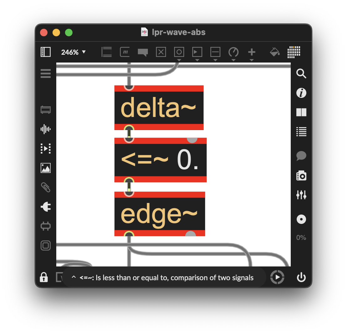
Figure 2-26
We will use this bang message to trigger recording using the record~ object, and also to control playback with the wave~ object. If we did this with a toggle object, the bang from 0. would start recording, turn it off, and play it —but it would cycle endlessly between record and play and record and play…
To avoid this problem, we need to create a structure where we have the bang message go into a gate, perform a series of actions for recording, then close that gate at the end of the loop, and open a different gate for the next bang message to start playback, and then close the second gate. To make the logic a little clearer, we’re going to unpack the sequence step by step:
- When we want to record, we “arm” record by opening the first gate object. This must happen before the loop starts.
- That gate allows a bang message through when the sync signal from the primary looper goes to 0., signaling the beginning of the loop
- This first bang message
- turns off any playback
- clears the contents of the buffer~ object in our secondary looper patcher
- Sends a message to set a live.text object to indicate that recording has been enabled, “Recording,”
- Triggers recording
- Opens gate 2
- Closes the first gate object so recording is not retriggered by more bang messages
Then…
- When the next bang message is let through the second gate, it
- Sends a message to set up the live.text object to indicate that recording has been disabled
- Disables recording,
- Starts playback
- Closes its own gate
As before, we’ll use trigger (t) objects to perform these actions quickly and in sequence.
This is the most complicated part of our new abstraction for secondary loopers/tracks. Let’s go over all four elements of the patcher and then see what the sequence of messages we’ll use trigger (t) objects to send:
Reset
- Turn off both of the gates with a “0”
- Disable playback by sending a “0” to a selector~ object that either lets the sync signal through or not. No signal means no playing back.
- Disable recording by sending a “0” to the record~ object
- Clear the buffer by sending a “clear” message to the buffer~ object
Arm/Record
- Enable recording by sending a “1” to the first gate. This gate allows a bang message through when sync hits 0. When the bang gets through at the beginning of the loop:
- Turn off playback by sending a “0” to the wave~ object
- Clear the buffer by sending a with a “clear” message to the to the buffer~ object
- Send a “1” message to set the live.text object to indicate recording has been enabled
- Starts record using the same “1” message and sending it to the record~ object
- Open Gate 2 by sending it a “1” message
- Close Gate 1 by sending it a “0” message
- Then the next bang at the end of the loop
- Set the live.tab outside the abstraction to “Play” with “2”
- Send a “0” message to set the live.text object to indicate that recording has been disabled
- Disable recording using the same “0” message and sending it to the record~ object
- Enable playback by sending a “1” to a selector~ object that allows the sync signal to pass through.
- Close Gate 2 by sending it a “0” message
Play
- Sends a “0” to ensure recording is off
- Sends a “1” to start play by opening the selector~ object that lets the sync signal through
Stop
- Disable playback by sending a “0” to a selector~ object that either lets the sync signal through
In the following patch, you’ll notice that we have added the same trapezoid~-based technique for declicking, as it is what we use in our original abstraction. It runs with the same shared sync signal.
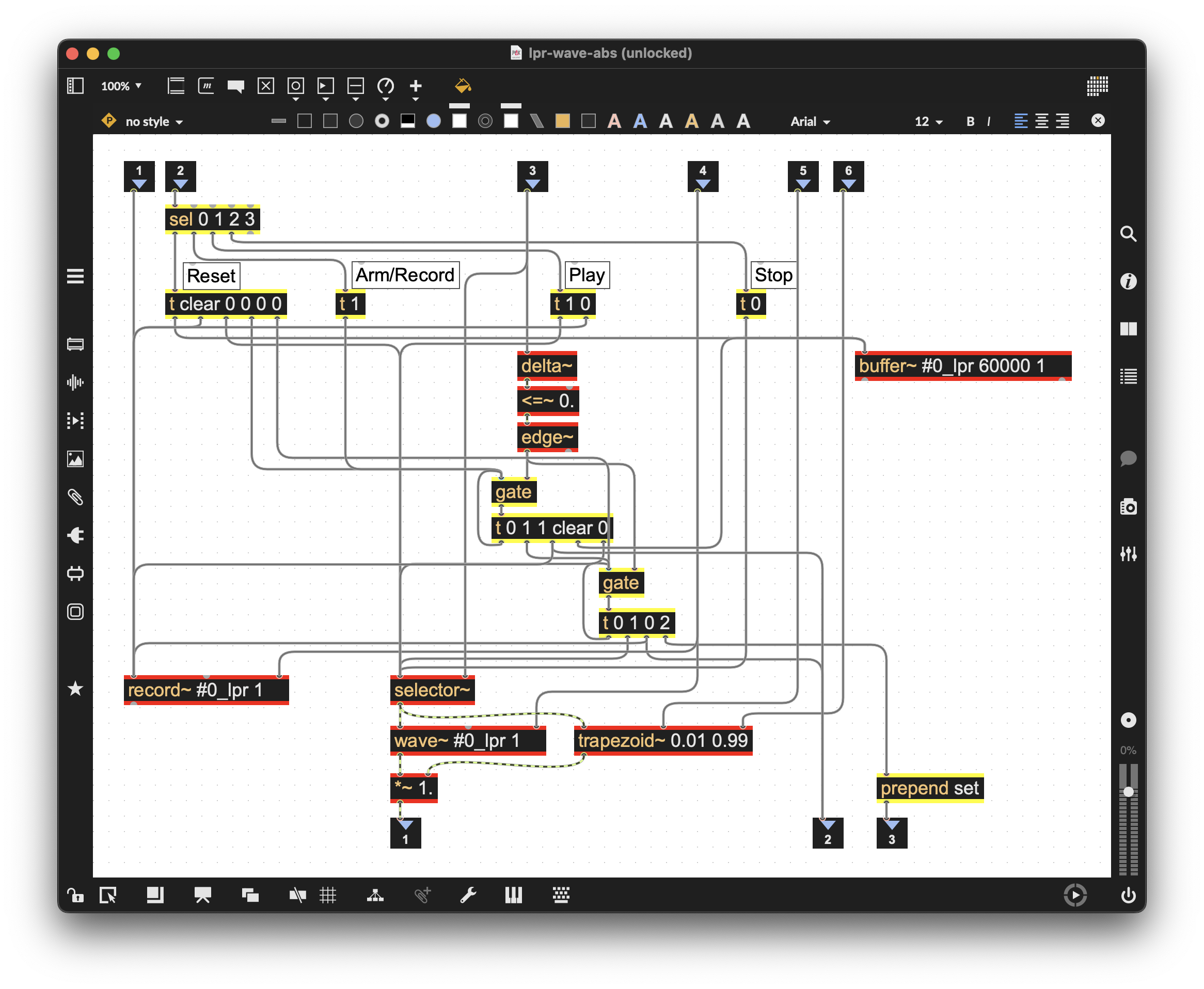
Figure 2-27
Performance UI
(Example Patcher: 2-8-Performance-UI)
As we’ve done with our previous looper, we use a live.tab object with the names of the four actions we need for our looper: Reset, Arm/Record, Play, and Stop. We’ve looked at the internals of our abstractions to verify the sequence of operations we need to perform, and we use a select (sel) object to pass a bang message as each mode is selected. There’s one detail to pay attention to: Since Play is set automatically in the abstraction following the recording of a loop, we’ll need to send a message “set 2” to the live.tab object that selects “Play” when play begins. (We use the “set” message to change this without outputting an index.) There is also a routepass object at the top of our patcher that is connected to our primary looper’s live.tab object output so that Reset will be selected on all the secondary loopers’ live.tab objects when Reset is selected on the primary looper.
We also have a live.text message to display “Recording” that is triggered when recording starts at the beginning of a loop and is then turned off when Play is automatically selected. Since the live.text objects in the secondary loopers are set by the primary looper’s output, clicking on the live.text objects in the secondary loopers is disabled by using the objects’ Inspectors and choosing the “Ignore Click” setting which turns them into display objects only..
Finally, we’ve added the same declicking patching using the trapezoid~ object and its controls to the secondary looper patchers.
Once we have connected our sync and loop max message, we’re ready to start looping.
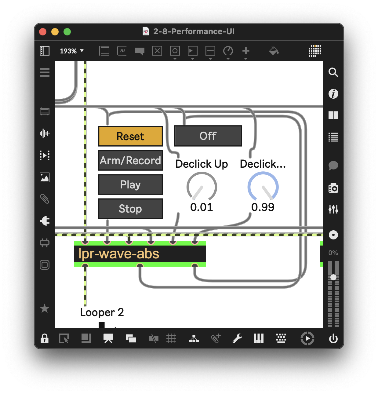
Figure 2-28
You can now copy and paste as many secondary looper patches as you’d like, and connect up the sync and loop outputs from the primary looper. For this example, we have a primary looper and three secondary loopers.
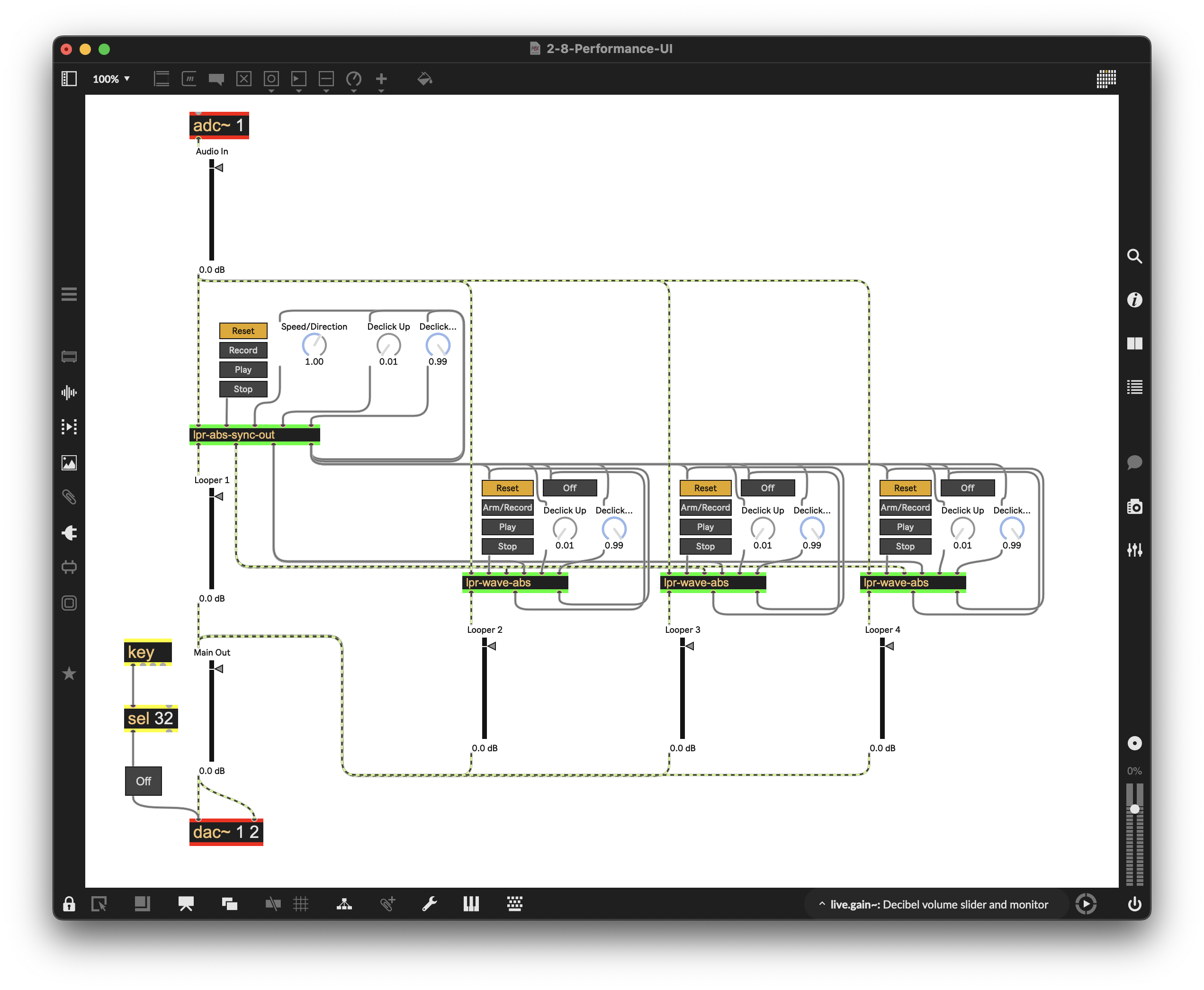
Figure 2-29
We have also added them to presentation mode to create a performance-ready interface.
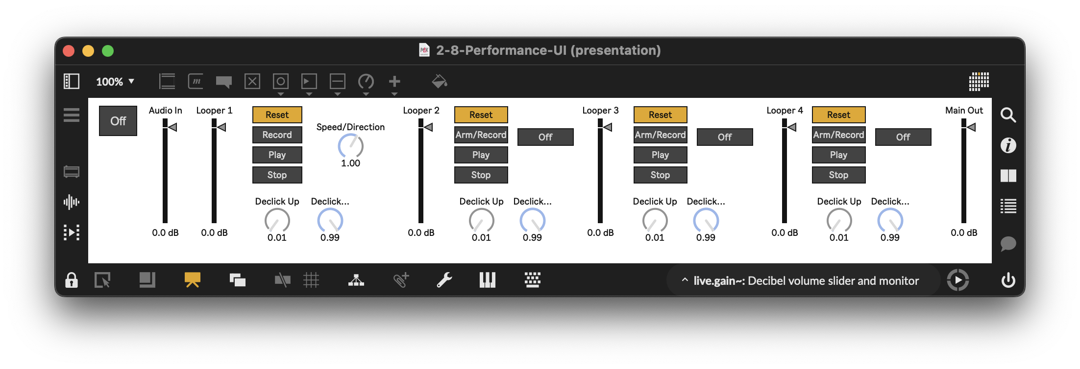
Figure 2-30
Here’s the advantage to this version of a multitrack looper: you can mix asynchronous and synchronous loopers in the same patch, and you can also process the audio of each track/loop separately for complex variations.
The main disadvantage is that although playback will always be synchronous at any speed, synchronous recording must always take place at normal speed. After you’ve recorded your input, you can change speed and direction as much as you want, and the audio will stay in sync.